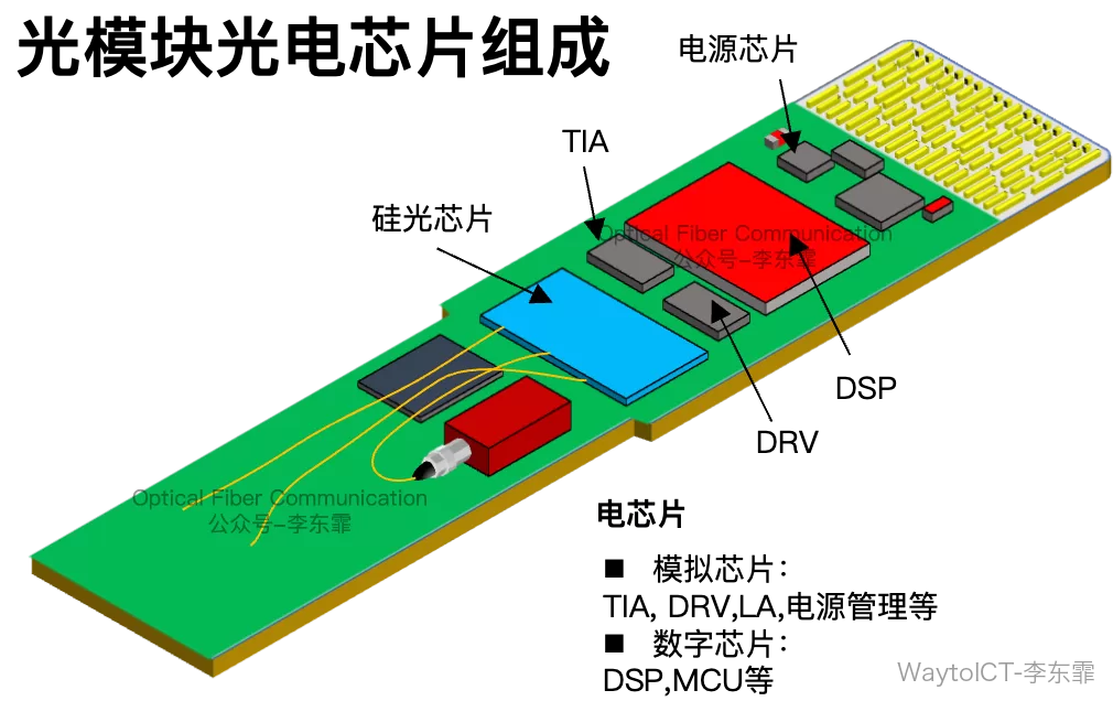
The electrical chips in high-speed optical modules fall into two major categories: analog and digital. On the analog side are the driver chip (DRV) on the transmit side and the transimpedance amplifier (TIA) on the receive side, responsible for amplifying and converting the optical-electrical signals.
On the digital side, the DSP does the heavy lifting: dispersion compensation, phase control, error correction, and pulse shaping.
Recommended reading:
Acacia/Cisco: DTCO and STCO co-optimization for high-speed optical modules
Among the analog chips, both the modulation voltage output by the DRV and the voltage converted by the TIA are high-speed analog signals that are very sensitive to parasitic parameters.
The interconnect between the PD and TIA must therefore be optimized as much as possible to reduce loss.
In the traditional approach, the TIA and PD are two separate chips connected by gold wire bonding, with the PD using top-side illumination.
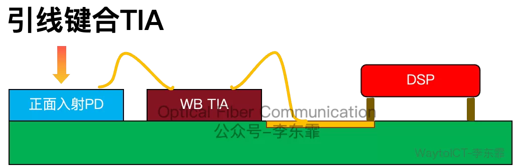
Wire bonding is mature and low-cost, but the parasitic capacitance and inductance introduced by the gold wire limit bandwidth and add loss and crosstalk.
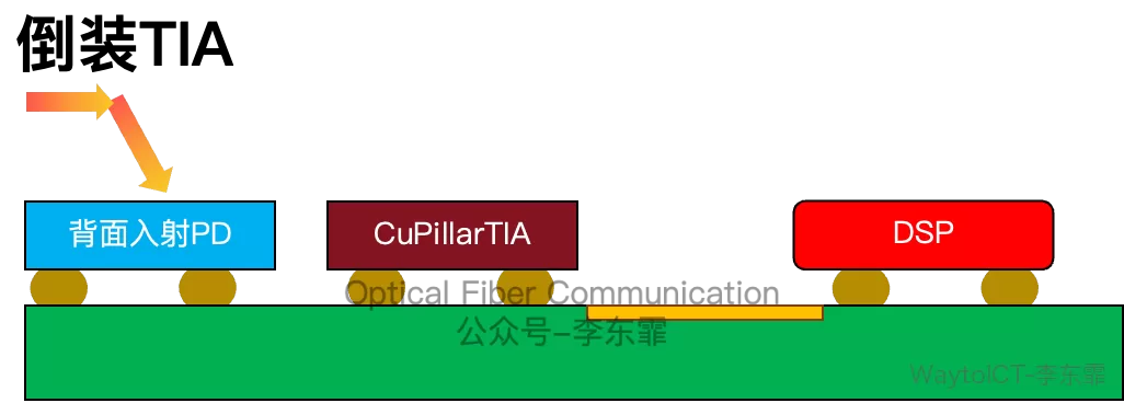
To reduce these parasitics, the flip-chip approach mounts the TIA and PD face-to-face via copper pillar bumps, eliminating the gold wire.
Recommended reading:
Accelink: EML package solution supporting flip-chip mounting
Corning: flip-chip CPO packaging progress on silicon-photonics PIC glass substrates
Innolight: thermal stress solution for flip-chip silicon photonics modules
Flip-chip mounting turns the TIA face down and solders it directly through copper pillars, with an extremely short interconnect distance, low parasitics, and high bandwidth — suitable for 800G/1.6T optical modules.
Another approach is 3D stacking, placing the back-illuminated PD directly on top of the wire-bonded TIA, though the TIA-to-DSP link still uses wire bonding.
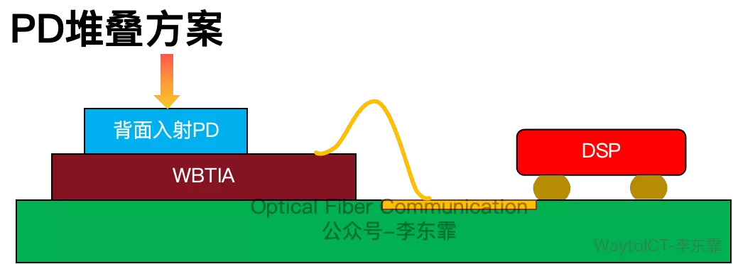
If the output side of the stacked approach is still wire-bonded, the parasitic limitation still exists.
At this year’s CIOE2026, MACOM showcased two generations of TIA products for 2.4T/3.2T based on these interconnect approaches.
The first generation has two versions — with and without a pre-integrated PD — but the TIA-to-DSP link still relies on gold wire bonding, so parasitic inductance limits the bandwidth; it is an early-stage solution.
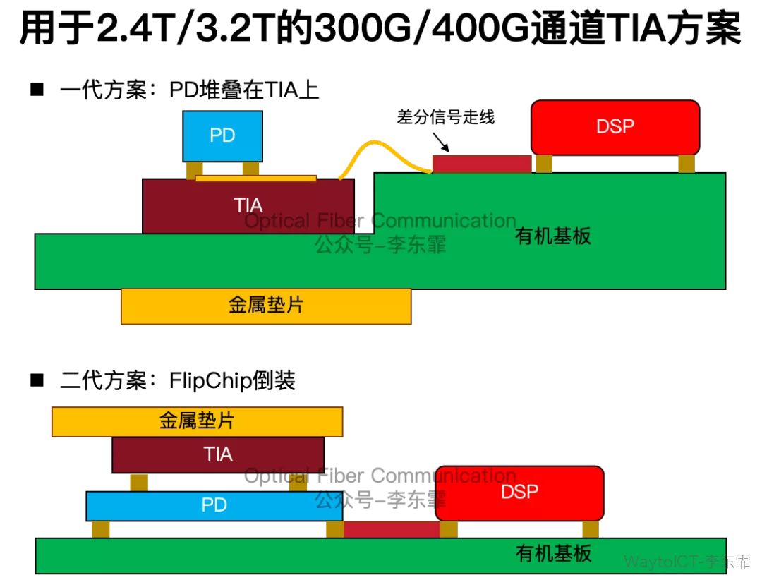
MACOM’s second generation flip-chips the TIA directly on top of the silicon photonics waveguide PD, removing this gold wire and further reducing loss.
The transmit chain, of course, must also meet bandwidth and signal-integrity requirements, relying on the modulator driver (DRV).
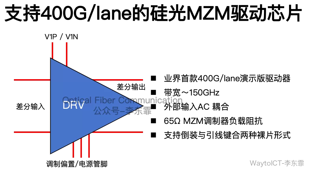
At CIOE2026, MACOM also demonstrated the industry’s first single-channel 400G/lane DRV chip.
Recommended reading:
Polaris: 400G silicon photonics MZM based on ferroelectric nematic glass
Coherent: single-channel 400G PAM4 pure-silicon MZM modulation solution
Hisense Ligent: 400G/lane LDO verification based on TFLN MZM
GlobalFoundries: single-wavelength 200G silicon photonics MZM solution
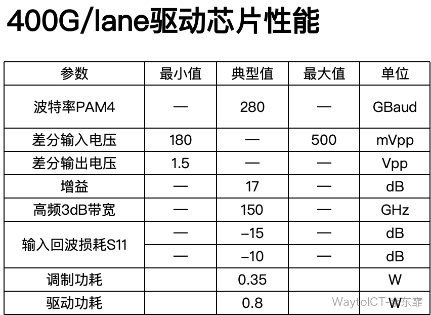
The device uses differential inputs and can support symbol rates up to 280 GBaud.
Measured performance reaches 390 Gbps PAM4 without offline signal processing, and 400 Gbps PAM4 after offline equalization compensates channel loss.
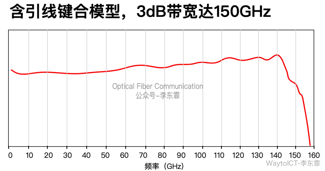
Including the wire-bond model, its 3 dB bandwidth reaches 150 GHz.
In addition to the DRV and TIA for PAM4 silicon-photonics IM-DD, MACOM is also pursuing a coherent-lite lightweight coherent route.
It supports MZM and TFLN modulators, and includes a driver and a low-noise TIA, with a focus on power optimization.
Compared with 400G-ZR, the driver power drops 47% and the TIA power drops 35%. This chipset does not include a DSP and must be paired with a third-party coherent DSP, targeting data center interconnect.
A brief record of MACOM’s DRV/TIA electrical chip situation at CIOE2026.
Thanks for reading.
Apologies for any inaccuracies!
Optical chips, optical devices, and optical modules (OFC2026) report compilation, color-printed and A4-bound, ~525 pages in two volumes, ~200,000 characters. Please contact us to order at an affordable price!
Enjoy this article?
Subscribe to get new optical communication insights delivered to your inbox. Free, unsubscribe anytime.