Optical fiber communication, due to its large communication capacity and long transmission distance, has become one of the main pillars of modern communication. Below is a wave of animations to give you a simple and intuitive understanding of the principles behind optical fiber communication.
1 Electromagnetic spectrum
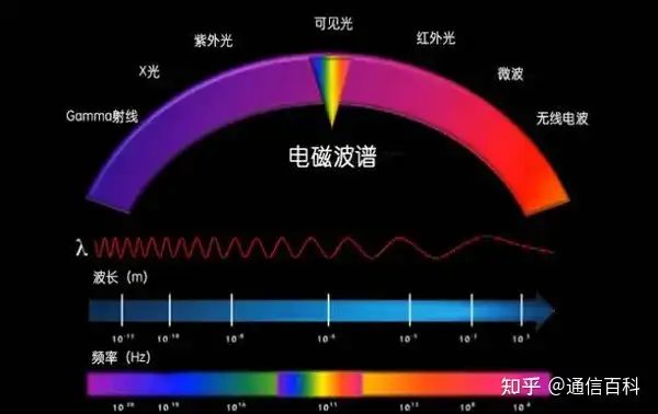
The operating wavelength of optical fiber communication is in the near-infrared region.
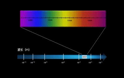
It is divided into the following bands: O band, E band, S band, C band, L band, and U band, as shown below:
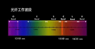
Reference article: Understanding Light 2 Fiber structure
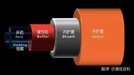
A bare fiber generally consists of the core, cladding, and coating layer.
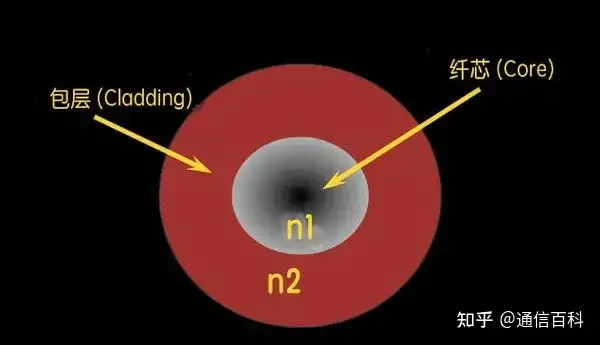
Reference article: The Structure of Optical Fiber
3 Total internal reflection in optical fiber
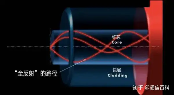
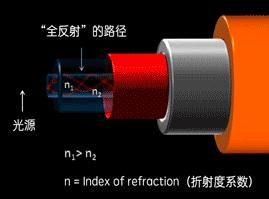
4 Single-mode fiber and multimode fiber
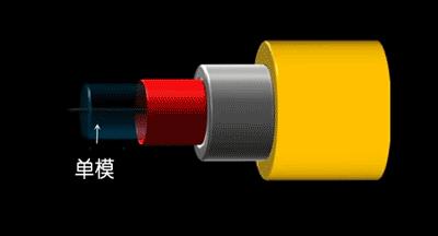
The outer diameter is generally about 125 um, and the inner diameter of single-mode is 9 um.
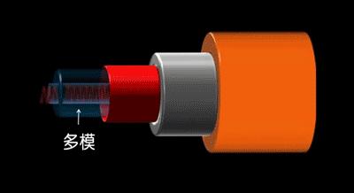
The outer diameter is generally about 125 um, and the inner diameter of multimode is 50/62.5 um.
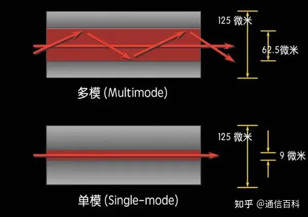
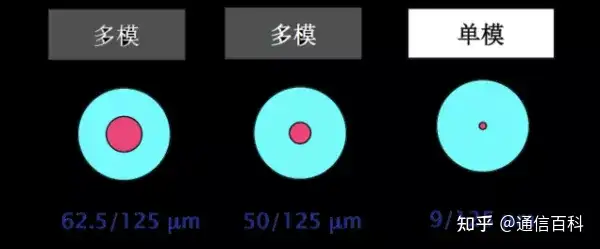
Reference article: Single-Mode Fiber / Multimode Fiber
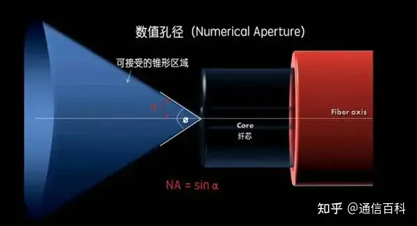
5 Numerical Aperture (NA) Only incident light within a certain angular range can be transmitted in the fiber. The sine of angle α equals the numerical aperture (NA = sinα).
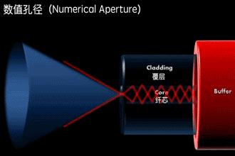
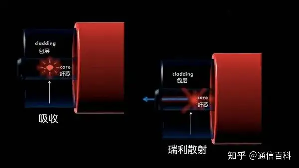
6 Light scattering The phenomenon of light deviating from its original propagation direction when passing through an inhomogeneous medium causes energy loss, which is called light scattering.
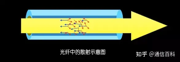
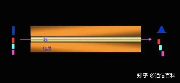
7 Rayleigh scattering Rayleigh Scattering is one type of scattering, also called “molecular scattering.” When the particle size is much smaller than the incident light wavelength (less than one-tenth of the wavelength), the intensity of scattered light in various directions is not the same, and this intensity is inversely proportional to the fourth power of the incident light wavelength. This phenomenon is called Rayleigh scattering.
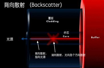
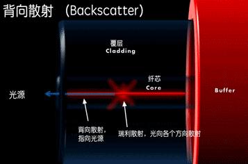
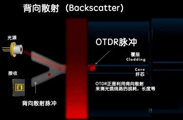
8 Backscatter
Backscatter refers to the fact that most of the optical power in the fiber propagates forward, but a small portion is scattered backward toward the light source. Using a beam splitter at the light source to observe the time curve of the backscatter, one can measure not only the length and attenuation of the connected uniform fiber from one end, but also detect local irregularities, breakpoints, and optical power loss caused by splices and connectors. OTDR, for example, uses this backscatter principle.
9 Fresnel reflection
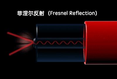
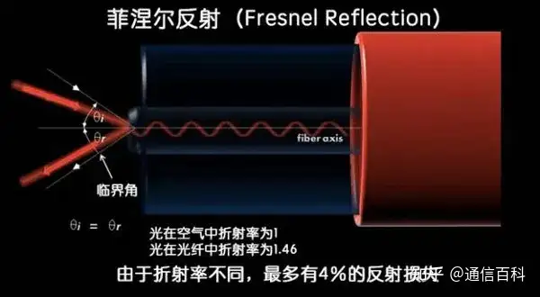
Fresnel Reflection refers to the phenomenon where part of the light is reflected when it enters the interface between two media with different refractive indices. If the transmission path of light in the fiber is fiber-air-fiber, since the refractive indices of fiber and air are different, Fresnel reflection will occur.
10 Chromatic dispersion (CD) Chromatic dispersion is caused by the fact that the silica glass fiber material has different refractive indices for different optical frequencies, and the light source has a certain spectral width, so different optical frequencies cause different group velocities, thus broadening the optical pulse. It includes material dispersion and waveguide dispersion.
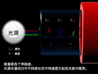
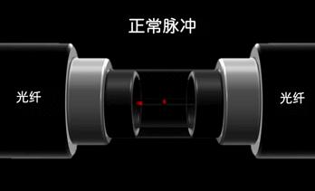
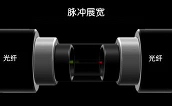
Reference: Phase Velocity and Group Velocity: Dispersion, Chromatic Dispersion CD in WDM Systems
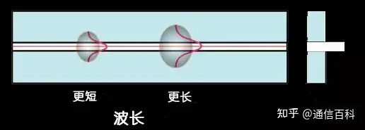
(1) Material dispersion Material dispersion is caused by the characteristics of the fiber material itself. Strictly speaking, the refractive index of silica glass is not a fixed constant, but has different values for different transmission wavelengths. The light emitted by the light source actually used in optical fiber communication is not only an ideal single wavelength, but has a certain spectral width.
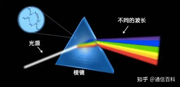
(2) Waveguide dispersion For a certain transmission mode of the fiber, the pulse broadening is caused by different group velocities at different optical frequencies. It is related to the waveguide effect of the fiber structure, so it is also called structural dispersion.
11 Refractive index of optical fiber
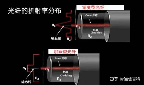
Reference article: Step-Index Fiber / Graded-Index Fiber 12 Mode field diameter (MFD) Mode Field Diameter is used to characterize the distribution of the fundamental mode light in the core region of a single-mode fiber. The fundamental mode has the maximum light intensity at the axis of the core region and gradually weakens as the distance from the axis increases. Generally, the mode field diameter is defined as the maximum distance between two points at 1/(e²) of the maximum light intensity at the axis.
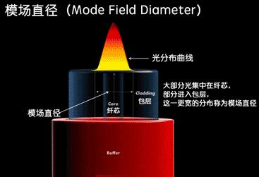
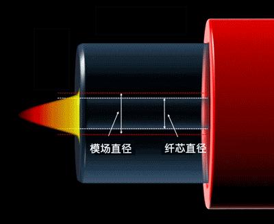
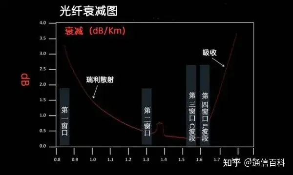
Reference article: Optical Fiber Communication: What Are Mode Field Diameter and Cutoff Wavelength? 13 Optical fiber attenuation Optical Attenuation, so-called loss, refers to the attenuation per unit length of the fiber, in dB/km. The level of fiber loss directly affects the transmission distance or the spacing of repeater stations. Therefore, understanding and reducing fiber loss is of great practical significance to optical fiber communication.
Fiber bending loss
Optical fiber is very sensitive to bending. If the bending radius is less than 20x the outer diameter, most of the light will leak from the coating. Both types of bending cause light loss: Macrobend and Microbend. Macrobend
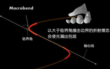
When the Macrobend is corrected, it can be recovered.
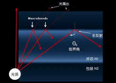
Microbend
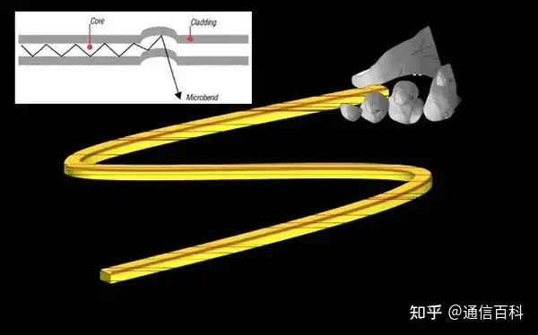
Microbend cannot be recovered, for example, caused by too-tight cable bundling.
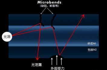
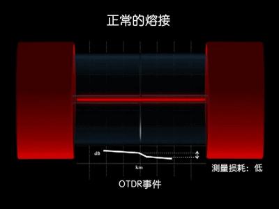
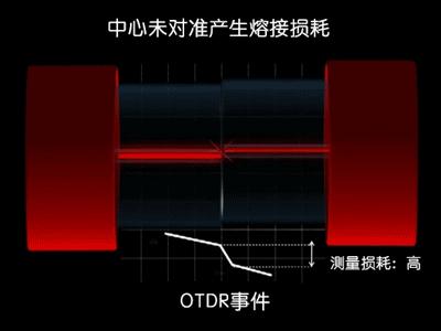
14 Fiber fusion splicing
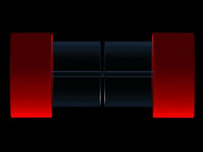
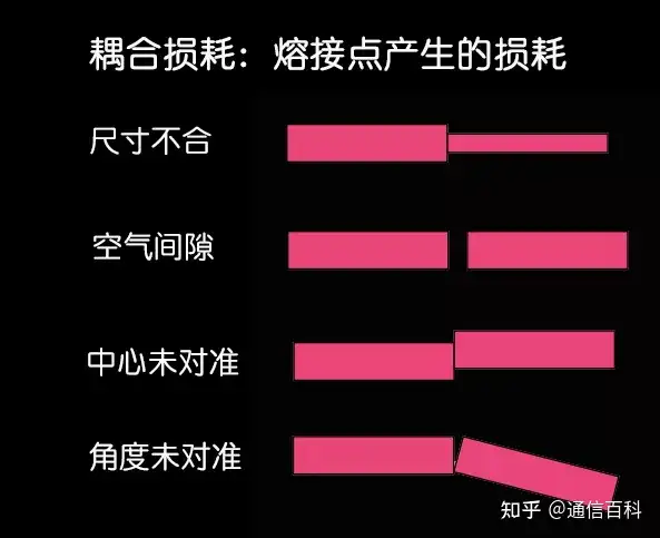
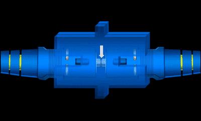
15 Fiber optic connectors
Fiber optic adapter
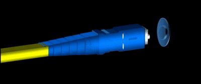
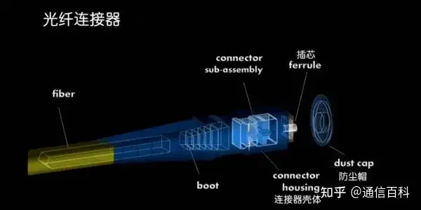
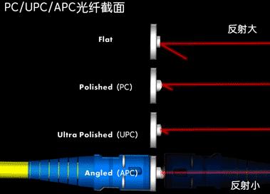
The cross-section of fiber connectors is divided into PC, UPC, and APC.
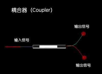
16 Coupler A fiber optic coupler is a passive optical device that splits an optical signal from one fiber into multiple fibers.
Related Reading
- What Is the Transmission Path of Light in an Optical Fiber?
- Optical Fiber Communication: The Structure of Optical Fiber
- Optical Fiber Communication: Mode Field Diameter and Cutoff Wavelength
Enjoy this article?
Subscribe to get new optical communication insights delivered to your inbox. Free, unsubscribe anytime.