The characteristic parameters of optical fiber can be divided into three major categories: geometric characteristic parameters, optical characteristic parameters, and transmission characteristic parameters, including attenuation coefficient (i.e., attenuation), dispersion, and nonlinear characteristics.
Attenuation Coefficient (Attenuation)
The attenuation coefficient is one of the most important characteristic parameters of multimode and single-mode fiber, largely determining the regeneration distance of multimode and single-mode optical fiber communication.
The attenuation coefficient is defined as the attenuation value of the optical signal power per kilometer of fiber. Its expression is:
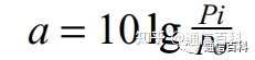
Unit: dB/km
Where Pi is the input optical power value (W) and Po is the output optical power value (W).
If a fiber has an attenuation coefficient of a = 3 dB/km, then lg(Pi/Po) equals 10 to the power of 0.3, approximately 2, meaning that after one kilometer of fiber transmission, the optical signal power value is reduced by half. The total attenuation of a fiber of length L kilometers is A = aL.
For single-mode fiber, an attenuation of 0.18 dB/km or even lower can now be achieved. For an optical signal, if the output power after EDFA amplification is +5 dBm and the receiver sensitivity is -28 dBm, the amplification gain is 33 dB. Divided by the attenuation coefficient, the distance is 33/0.18 = 183 km; considering aging and other margins, the actual transmission distance is somewhat smaller.
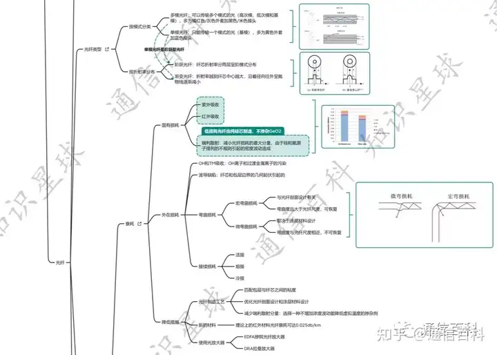
There are many causes of fiber attenuation, mainly including: absorption attenuation, including impurity absorption and intrinsic absorption; scattering attenuation, including linear scattering, nonlinear scattering, and structural-imperfection scattering; and other attenuation, including microbend attenuation. The most important is impurity absorption. Impurities in the fiber material, such as hydroxyl ions and transition metal ions, have extremely strong absorption of light and are important factors causing optical signal attenuation.
Therefore, to obtain low-attenuation fiber, the silica raw material used to manufacture the fiber must undergo very strict chemical purification to reduce impurity content to below a few PPb. The Composition of Fiber Loss and How to Reduce Fiber Loss.
Dispersion
When an optical pulse is input into a fiber and transmitted over a certain length, the output optical pulse becomes wider and even obviously distorted. This indicates that the fiber broadens the optical pulse, i.e., the fiber has dispersion. This is mainly because the front and rear ends of the optical pulse travel different distances in the fiber, causing pulse broadening.

Fiber dispersion is the main cause of narrowing fiber bandwidth, which limits the transmission capacity of the fiber and also limits the transmission distance of the optical signal.
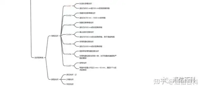
G.652 fiber has zero dispersion at the 1310 nm window and dispersion at the 1550 nm window; when transmitting 10G signals, dispersion-compensating fiber is needed for dispersion compensation. G.653 fiber is dispersion-shifted fiber with zero dispersion at the 1550 nm window, which can transmit 10G optical signals, but when transmitting WDM signals, due to zero dispersion, nonlinear effects such as four-wave mixing occur, so it cannot be used for WDM transmission. G.655 fiber has very small dispersion at the 1550 nm window and can be used for SDH optical signals and WDM signal transmission.
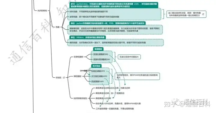
Fiber dispersion can be divided into three parts: modal dispersion, material dispersion, and waveguide dispersion.
- Modal dispersion: mainly for multimode fiber. For single-mode fiber, since only one mode propagates, there is no modal dispersion problem.
- Material dispersion: refers to the dispersion produced by silica, the material composing the fiber.
- Waveguide dispersion: refers to the dispersion caused by the waveguide structure of the fiber.
The definition of modal dispersion: when multimode light is transmitted in a multimode fiber, many transmission modes exist, and each transmission mode has a different propagation speed and phase. Therefore, although optical pulse signals are input simultaneously at the input end, the arrival times at the receiving end are inconsistent, producing pulse broadening, called modal dispersion.
For multimode fiber, since its modal dispersion is relatively severe and its value is large, its material dispersion is small and not dominant, and waveguide dispersion has very little effect on multimode fiber. Therefore, multimode fiber mainly considers modal dispersion. Single-mode fiber transmits a single mode with no modal dispersion (modal dispersion is zero), so material dispersion and waveguide dispersion are considered. The pulse broadening caused by total fiber dispersion can be calculated by the following formula:

Dispersion is mainly represented by the dispersion coefficient D(λ). The dispersion coefficient is generally only for single-mode fiber and includes material dispersion and waveguide dispersion, collectively called the dispersion coefficient.
Definition of the dispersion coefficient: the pulse broadening value per kilometer of fiber caused by unit spectral width, linearly related to length. Its calculation formula is:

Where δλ is the light source spectral width (a fuzzy concept that can be ignored as long as it is consistent before and after), D(λ) is the dispersion coefficient, and L is the length. The current single-mode fiber dispersion coefficient is generally 20 ps/km·nm. The longer the fiber length, the greater the total dispersion. The smaller the dispersion coefficient, according to the above formula, the larger the fiber bandwidth and the larger the transmission capacity.
Therefore, when transmitting optical signals above 2.5G, the impact of fiber dispersion on transmission distance should be considered. It is best to use zero-dispersion G.653 fiber for transmission, but when fiber dispersion is zero, transmitting WDM signals will produce nonlinear effects such as four-wave mixing, so dispersion should be small but not zero. The final fiber adopted is G.655 fiber to transmit 10G optical signals and WDM multiplexed signals.
For single-mode fiber, the bandwidth coefficient is above 25 GHz·km, but the bandwidth coefficient of multimode fiber is generally below 1 GHz·km. Therefore, multimode fiber is generally used for short-distance communication below 622M, while single-mode fiber can be used for various rates of communication. Understanding “Single-Mode” and “Multimode” in Fiber Lasers Through Multiple Image Comparisons.
Bandwidth Bc, Numerical Aperture NA, Mode Field Diameter d, and Cutoff Wavelength λc
Bandwidth is mainly represented by the bandwidth coefficient Bc. Through experiments, it can be found that if the input optical signal power remains unchanged, as the modulation frequency increases, after transmission through the fiber, the output optical power decreases with increasing modulation frequency at the transmitter. This indicates that the fiber also has a bandwidth coefficient like cable, i.e., a certain response characteristic to the modulation frequency of the modulated optical signal. Like cable, there is a distinction between high-frequency and low-frequency lines, and the attenuation of high-frequency and low-frequency lines is also different.
Definition of the bandwidth coefficient: for a one-kilometer fiber, when the output optical signal power drops to half of its maximum value (the output optical power with DC optical input), the modulation frequency of the optical signal at this time is called the fiber’s bandwidth coefficient, i.e., the bandwidth of the optical signal when it drops by half, also called the 3 dB bandwidth. For DWDM equipment, there are also characteristic tests of 0.5 dB bandwidth, 1 dB bandwidth, and 20 dB bandwidth.
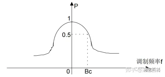
It should be noted that optical signals are measured in optical power, generally in dBm, and can also be expressed in watts (W). W and dBm are mutually convertible, with the conversion formula dBm = 10lgW; 1 mW is 0 dBm, and 500 uW is about -3 dBm.
So the 3 dB bandwidth is the bandwidth when the optical signal output power is reduced by half. Similarly, for cable, 6 dB bandwidth is generally used to represent the halving of electrical energy attenuation, because electrical signals are measured in voltage or current, calculated with 20lg.
The main cause of narrowing fiber bandwidth is fiber dispersion. For multimode fiber, multimode optical signals are transmitted, and the bandwidth is also called modal dispersion bandwidth, with the bandwidth coefficient representing the transmission capability of multimode fiber. For single-mode fiber, since modal dispersion is zero, there is also the concept of bandwidth coefficient, while introducing the concept of dispersion coefficient. Due to the improvement of single-mode fiber manufacturing technology, its dispersion coefficient is generally 20 ps/km·nm.
For single-mode transmitting lasers, a dispersion tolerance parameter is given, such as 7200 ps, then 7200/20 = 360 km, indicating that this laser can transmit 360 km without electrical regeneration. For SDH transmission, without electrical regeneration, it generally does not exceed 150 km, and the dispersion tolerance parameter is generally not considered; only in DWDM is this parameter considered. In DWDM, the maximum transmission without electrical regeneration is 640 km, so the required dispersion tolerance must be above 12800 ps/km.
For fiber, the relationship between bandwidth and dispersion can be approximately expressed as:
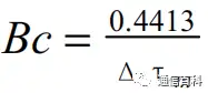
Δτ is the modal dispersion of the fiber. Obviously, fiber bandwidth is related to dispersion and has a nonlinear relationship with length, while fiber attenuation is linearly related to length.
The bandwidth coefficient Bc is an important parameter describing fiber transmission characteristics in the frequency domain, actually continuing the concept of analog communication. For multimode fiber, the root-mean-square spectral width δf is generally used to express the bandwidth coefficient characteristic during measurement; for single-mode fiber, the 3 dB and 20 dB spectral width characteristics are generally measured to express the bandwidth coefficient characteristic.
Physical definition of the root-mean-square spectral width of fiber: the value of the independent variable time t corresponding to 0.61 times the maximum function value of the Gaussian impulse response of the fiber. On one hand, in practical work, measuring in the time domain is more convenient and feasible than in the frequency domain; on the other hand, the root-mean-square δf of the fiber has a closer relationship with digital optical fiber communication theory and is directly related to the root-mean-square pulse width of the transmitted optical pulse. The root-mean-square spectral width can not only accurately describe the characteristics of optical pulses, but is also closely related to the transmission regeneration distance of optical fiber communication systems, so it is often used in optical fiber communication theory.
Numerical Aperture NA
The numerical aperture is an important parameter of multimode fiber, characterizing the fiber end face’s ability to receive light. Its value should balance the fiber’s ability to receive light and the impact on modal dispersion. According to the principle of total internal reflection, the physical meaning of NA is the sine of the acceptance angle θc at which light signals can propagate in the fiber in the form of total internal reflection.
The NA of the fiber is not the larger the better. The larger the NA, the stronger the fiber’s ability to receive light, but the more severe the modal dispersion of the fiber. Because the larger the NA, the larger its relative refractive index difference, leading to greater modal dispersion, reducing transmission capacity and distance. There are regulations on the NA value of the fiber; CCITT recommends the fiber NA be between 0.18 and 0.24.
What Are Mode Field Diameter and Cutoff Wavelength? The mode field diameter d characterizes the degree to which a single-mode fiber concentrates optical energy. A single-mode fiber allows only one mode, the fundamental mode, to transmit, and its mode field diameter d is calculated as:
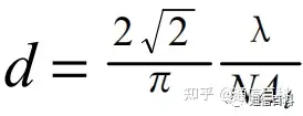
Where λ is the optical wavelength (um) and NA is the maximum theoretical numerical aperture of the single-mode fiber. Through calculation, loosely speaking, the mode field diameter d is close to the core diameter of the single-mode fiber.
Cutoff Wavelength λc
The meaning of the cutoff wavelength is the minimum operating optical wavelength that enables the fiber to achieve single-mode transmission. If the wavelength of the optical signal to be transmitted is not greater than the cutoff wavelength of the single-mode fiber, single-mode transmission cannot be achieved.
Nonlinear Effects in Fiber Transmission
Attenuation and dispersion in fiber transmission change linearly with fiber length, which are linear effects, while the bandwidth coefficient has a nonlinear effect with fiber length. What Are Nonlinear Effects in Optical Fiber?
Nonlinear effects are generally more apparent in WDM systems and less in SDH systems. Because in WDM systems, the insertion loss of the multiplexer and demultiplexer is large, about 10 dB for a 16-wave system and about 15 dB for a 32-wave system, EDFA amplification is needed for compensation. However, while amplifying the optical power, the nonlinear effects in the fiber are also greatly increased, becoming one of the main factors affecting system performance and limiting regeneration distance, and also increasing noise such as ASE.
Nonlinear effects in the fiber include:
- Scattering effects (stimulated Brillouin scattering SBS and stimulated Raman scattering SRS, etc.)
- Effects related to the Kerr effect, i.e., closely related to the refractive index (self-phase modulation SPM, cross-phase modulation XPM, and four-wave mixing FWM), among which four-wave mixing and cross-phase modulation severely affect the system.
A. Stimulated Brillouin Scattering SBS and Stimulated Raman Scattering SRS
Essentially, any substance is composed of basic units such as molecules and atoms. At room temperature, these basic units are constantly undergoing spontaneous thermal motion and vibration. Stimulated Brillouin scattering SBS and stimulated Raman scattering SRS in fiber are both the result of laser light waves being modulated by molecular vibrations when passing through the fiber medium, and both SBS and SRS have gain characteristics; under certain conditions, this gain can accumulate along the fiber. The difference between SBS and SRS is that SBS excites acoustic phonons, while SRS excites optical phonons.
Principle of stimulated Brillouin scattering SBS: SBS is the result of the interaction between pump light and phonons in the fiber. In intensity-modulated systems using narrow-linewidth light sources, once the signal optical power exceeds the SBS threshold (the SBS threshold is low, generally 7-8 dBm for a 1550 nm laser), a strong forward-transmitting signal light will be converted into backward transmission, and as the forward transmission power gradually saturates, the backward scattering power sharply increases.
In a WDM+EDFA system, the power injected into the fiber exceeds the SBS threshold, producing SBS scattering. The impact of SBS on WDM systems is mainly causing crosstalk between system channels and loss of channel energy. The Brillouin frequency shift at 1550 nm is about 10-11 GHz.
When the channel spacing (i.e., wavelength spacing) of the WDM system equals the Brillouin frequency shift, crosstalk between channels occurs. However, in current WDM systems with 32 waves or fewer, the channel spacing is not less than 0.8 nm, i.e., not less than 100 GHz, which can avoid channel crosstalk caused by SBS. As WDM develops toward higher density, channel spacing becomes smaller; when the channel spacing approaches 10-11 GHz, SBS will become the main factor of channel crosstalk.
In addition, since SBS causes part of the channel power to transfer to noise, it affects power amplification. The current measure to suppress SBS is usually to add a low-frequency modulation signal at the laser output to raise the SBS threshold.
Principle of stimulated Raman scattering SRS: stimulated Raman scattering SRS is a broadband effect related to the interaction between light and the vibrational modes of silicon atoms. In any case, short-wavelength signals are always attenuated by this process, while long-wavelength signals are enhanced.
Stimulated Raman scattering SRS can occur in both single-channel and multi-channel systems. In a system with only a single channel and no line amplifier, when the signal power exceeds 1 W, the power is damaged by this phenomenon. In multi-channel systems with wider channel spacing, shorter-wavelength signal channels transfer part of their optical power to longer-wavelength signal channels due to SRS, possibly causing degradation of signal-to-noise ratio performance.
Since stimulated Raman scattering SRS excites optical phonons, the Raman frequency shift it produces is much larger than the Brillouin frequency shift, generally 100 GHz-200 GHz, and the threshold is large, about 27 dBm at 1550 nm. It generally does not occur. But for WDM systems, as the transmission distance grows and the number of multiplexed waves increases, the optical signal power output by EDFA amplification will approach 27 dBm, increasing the probability of SRS occurrence.
Because the equivalent core area of G.653 fiber is smaller than that of G.652 fiber, the SRS threshold is lower than systems using G.652 fiber, and the probability of SRS occurring on G.653 fiber is greater.
B. Self-Phase Modulation SPM and Cross-Phase Modulation XPM
The Kerr effect in fiber is a nonlinear effect of the refractive index, i.e., the change in laser intensity in the fiber causes a change in the fiber’s refractive index, causing the phase adjustment of the optical signal itself. This effect is called self-phase modulation.
Due to the dependence of the refractive index on light intensity, the refractive index changes during the optical pulse duration, and the phase of the pulse peak is delayed relative to both the leading and trailing edges. This phase shift accumulates with increasing transmission distance, and after reaching a certain distance, it exhibits considerable phase modulation, thereby broadening the spectrum and causing pulse broadening. This is called self-phase modulation SPM. In DWDM systems, spectral broadening is very severe and can cause the pulse spectrum of one channel to overlap with that of another channel, affecting system performance.
Generally, the self-phase modulation SPM effect is only more apparent in ultra-long systems and is also more apparent in fibers with large dispersion. Therefore, using G.653 fiber and setting the channel near the zero-dispersion region helps reduce the SPM effect. For systems using G.652 fiber with a length of less than 1000 km, the SPM effect can be controlled by dispersion compensation at appropriate intervals.
In multi-wavelength systems, the phase change of one channel is related not only to its own light intensity but also to the light intensity of other adjacent channels. Due to the interaction between adjacent channels, the phase change of mutual modulation is called cross-phase modulation XPM. The spectral broadening caused by XPM is related to the channel spacing; the smaller the spacing, the greater the effect, and vice versa. The broadening caused by XPM leads to interference between adjacent channels in multi-channel systems.
The effects of SPM and XPM in fibers with large dispersion are greater than in fibers with small dispersion. In practical systems, the SPM and XPM effects can be reduced by using G.653 and G.655 fibers with small dispersion.
C. Four-Wave Mixing
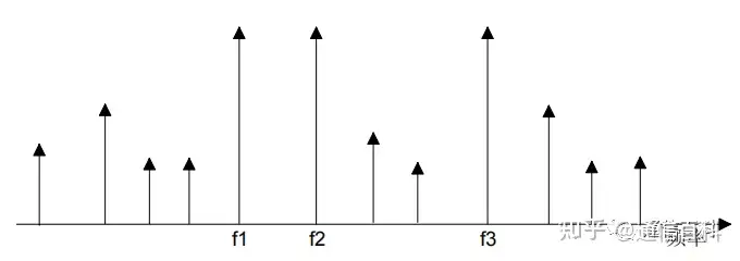
Four-wave mixing (FWM), also called four-phonon mixing, is an optical-wave coupling effect produced by the real part of the third-order polarization of the fiber medium. It is the interaction of two or three light waves of different wavelengths that produces so-called mixing products or new sideband light waves at other wavelengths. This interaction can occur between signals in multi-channel systems and can produce various parametric effects such as frequency tripling, sum frequency, and difference frequency.
In DWDM systems, when the channel spacing and fiber dispersion are sufficiently small and phase matching is satisfied, four-wave mixing becomes the main factor of nonlinear crosstalk. When the channel spacing reaches below 10 GHz, the impact of FWM on the system is most severe. The figure below shows the four-wave mixing effect with three signals:
The impact of four-wave mixing FWM on DWDM systems is mainly manifested in:
(1) Generating new wavelengths, causing the optical energy of the original signals to be lost, affecting system performance such as signal-to-noise ratio;
(2) If the newly generated wavelength is the same as or overlaps with an original wavelength, severe crosstalk occurs.
The generation of four-wave mixing FWM requires phase matching of the signal lights. When the signal lights transmit near the zero dispersion of the fiber, the impact of material dispersion on phase mismatch is small, so the phase matching condition is easier to satisfy, making four-wave mixing more likely to occur.
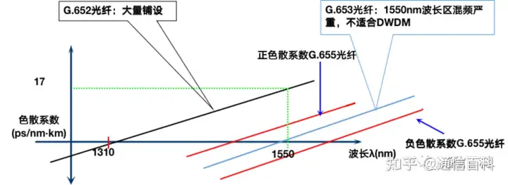
The channel spacing of current DWDM systems is generally 100 GHz. Zero dispersion causes four-wave mixing to become the main factor, so when using G.653 fiber for DWDM system transmission, four-wave mixing is likely to occur, while using G.652 or G.655 fiber, four-wave mixing is less likely to occur.

Related Reading
- What Is the Transmission Path of Light in an Optical Fiber?
- Optical Fiber Communication: The Structure of Optical Fiber
- Optical Fiber Communication: Mode Field Diameter and Cutoff Wavelength
Enjoy this article?
Subscribe to get new optical communication insights delivered to your inbox. Free, unsubscribe anytime.