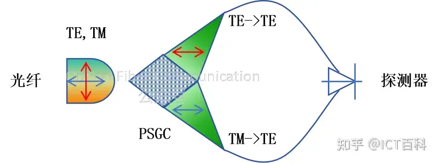
In transmitter applications, the laser is tightly integrated with the circuit, keeping the light source single-polarized. Whether it is TE light or TM light, it can be efficiently coupled into a single-mode fiber. For silicon photonic devices, TE-mode light is generally preferred for transmission.
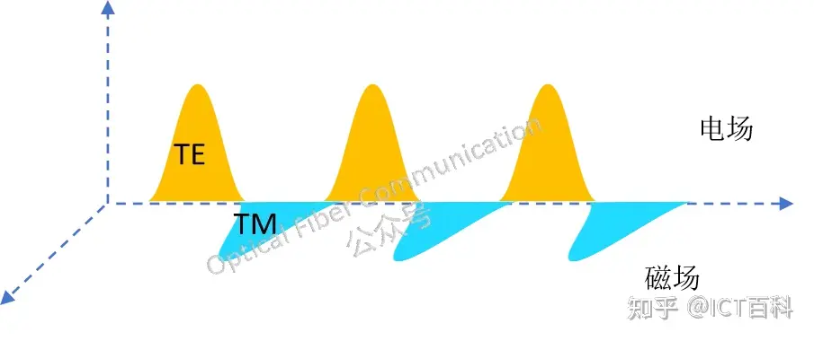
Reference: Why Is the TE Mode Preferred over the TM Mode in Silicon Photonic Waveguides?
However, at the receiving end, light passing through a single-mode fiber is affected by temperature and strain changes, causing the polarization state to be unable to be maintained and producing slow time variation. Especially after passing through fiber, bending and strain both cause coherent crosstalk and polarization-mode coupling, producing random birefringence.
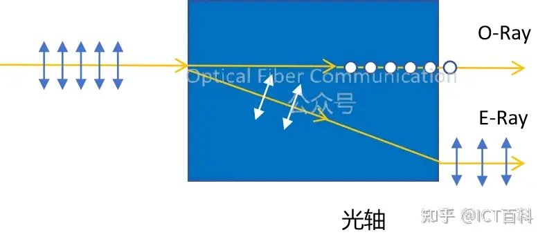
So, how can we make the receiving-end circuit insensitive to polarization?
One simple method is to use polarization-maintaining fiber, where polarized light can be called o-light and e-light, or more commonly p-light and s-light.

But polarization-maintaining fiber is not advantageous in cost, especially in multi-wavelength laser applications, where the required amount of polarization-maintaining fiber increases and the requirements for waveguide structure design are also higher.
In addition, in on-off-keying (OOK) systems, signals are transmitted by switching between “light on” and “light off.” As long as the detector can detect the presence or absence of light, the original digital signal can be recovered without considering the polarization state of the light.
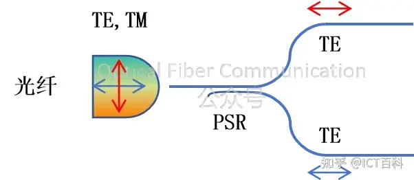
Another approach is to use a polarization-diversity scheme, such as using a polarization-splitting grating coupler (PSGC) or a polarization splitter-rotator (PSR). That is, first separate the polarization state of the light through a polarization-splitting grating or rotator, and output it to two TE-polarized waveguides.
For example, using a grating coupler to achieve polarization diversity:
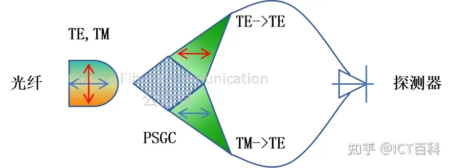
A polarization splitter-rotator (PSR) can also be used to achieve polarization diversity:
If the light needs to be coupled back into the fiber, two completely identical circuits can be used, including matched ring resonators or filters.
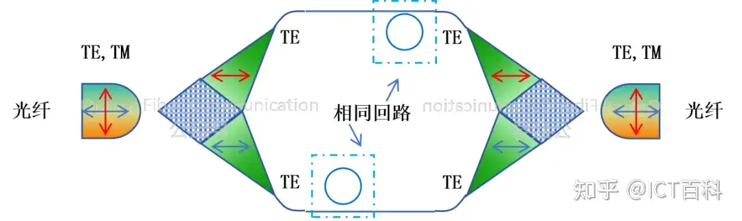
The polarization-diversity scheme above requires two photonic circuits, which increases chip area and power consumption. Can we use only one photonic circuit?
An active polarization-management method can be adopted, using an active polarization controller and two phase shifters to adjust the phase and amplitude of the TE and TM polarizations in the fiber to achieve matching.
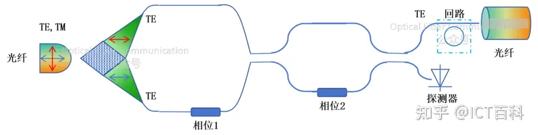
This scheme can not only convert light of any polarization state into a single TE polarization but can also produce any desired polarization output state in the reverse process.
Thank you for reading. If there are any inaccurate statements, please forgive me and leave a comment to point them out. Thank you!
Related Reading
- Silicon Photonics Series 1: How to Smoothly Couple Light from Fiber into the Waveguide?
- Why Is the TE Mode Preferred over the TM Mode in Silicon Photonic Waveguides?
- Passive and Active Polarization Management: Intel’s Silicon Photonic Polarization-Diversity Receiving Scheme
Enjoy this article?
Subscribe to get new optical communication insights delivered to your inbox. Free, unsubscribe anytime.