The importance of semiconductors needs no detailed explanation; you can imagine that all electronic products in daily life use semiconductor devices.
Among these, a common indicator we care most about for these products is: how long can this thing last?
Can we let users test this for us? Of course not, unless it is a one-time deal.
To keep a product from being awkward in the market, we have to start with product reliability. That is, we need to perform reliability testing, one of the three major tests in chip manufacturing.

So what is reliability? Let me quote a passage from a specification:
“Reliability” is a broad concept. Taking plastic-encapsulated chips as an example, “reliability” in the narrow sense generally refers to chip-level reliability, including circuit-related reliability (ESD, Latch-up, HTOL) and packaging-related reliability (PC, TCT, HTSL, HAST, etc.). But chips often do not “operate independently” in application scenarios; instead, they serve as a component on a PCB in a product solution as the final application.
Therefore, reliability is divided into chip-level reliability and product-level reliability.
In terms of evaluation standards, we usually use MTBF (Mean Time Between Failures) and MTTF (Mean Time To Failure) to measure product reliability.
Below, let us briefly look at how MTTF is calculated.
For a group of non-repairable products, suppose we have N0 products, and each product fails at time Ti. Then the formula for calculating MTTF is:

- N0 is the number of failed products;
- Ti is the elapsed time when the i-th product fails.
For example, suppose there are 5 non-repairable products that fail at 1000 hours, 1500 hours, 2000 hours, 2200 hours, and 2300 hours respectively, then MTTF can be calculated using the above formula.
Here, careful readers may notice that we emphasized “non-repairable products,” referring to certain discrete devices or single-use devices. For ICs, storage devices, power management units, chips, etc., MTBF is more commonly used. Interested friends can leave a comment about how MTBF is calculated.
For semiconductor chips, it describes the average length of time, or the failure probability, that a chip can run continuously without failure under its expected operating conditions. In the industry, we usually use the bathtub curve model to describe the changing trend of a product’s failure rate over its entire life cycle. Of course, this model is also widely used in reliability testing in other industries.
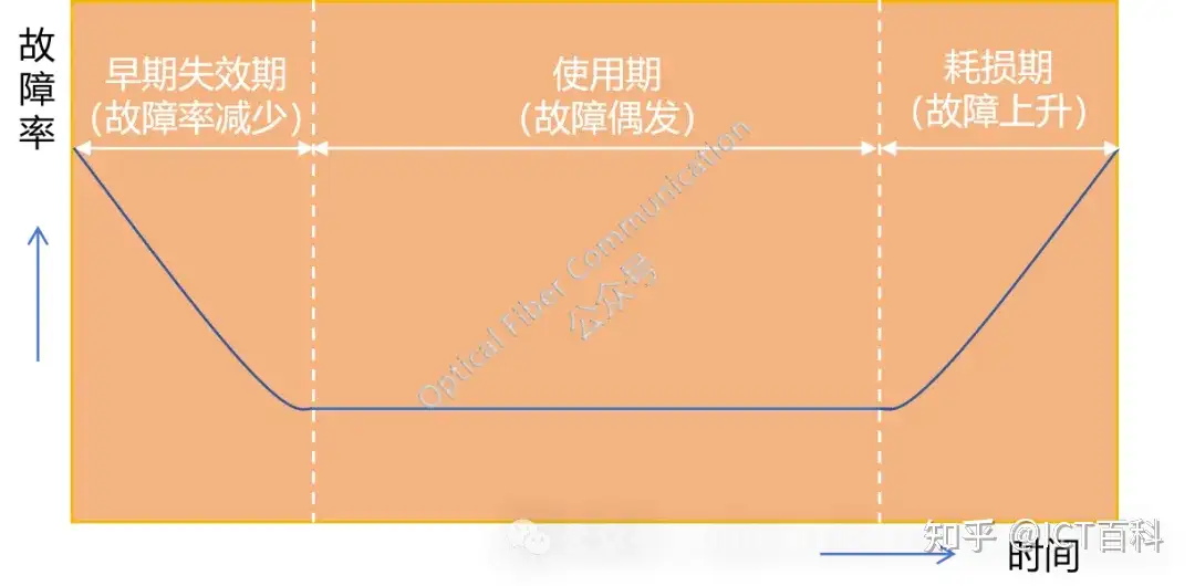
As shown in the figure above, the bathtub curve model consists of three stages:
- Early failure period: in the initial stage, the failure rate is relatively high due to manufacturing defects and other reasons. This stage corresponds to MTTF, that is, the average time from product shipment to first failure.
- Useful life period: during this period, qualified products after screening have a relatively low and stable failure rate. The MTBF in this stage is most pronounced, because it represents the average time between two consecutive failures within this time period.
- Wear-out period: as time and usage conditions take effect, components gradually age and the failure rate rises again. MTTF or MTBF is equally applicable at this point, but mainly reflects the situation where equipment approaches the end of its service life.
It can be imagined that taking the above bathtub soak would take a very, very long time. Therefore, we have to find a way to artificially accelerate this process, creating something like a time machine: the burn-in test system. Burn-in testing is exactly meant to simulate and accelerate the process of entering the wear-out period, so as to detect potential reliability problems in advance. But it should be understood that burn-in testing is a specific form of reliability testing, not the entirety of reliability testing.
Whether it is burn-in or other tests, the key for a product is how to detect early defects, that is, quality assurance targeting early failure. If a product has a large number of failures right after launch, the manufacturer is not far from going out of business.
Let me give another example: Apple’s iPhone X series caused performance problems due to insufficient burn-in testing, damaging its market. I wonder if anyone still remembers this?
Back to the topic. Burn-in testing requires sufficiently rigorous and more stringent-than-normal testing, such as applying voltage, current, or temperature higher than normal operating conditions, to prompt the chip to exhibit, in a short time, failure phenomena that might only appear after long-term use. By monitoring the performance changes of the chip under extreme conditions, engineers can identify potential failure modes and mechanisms, such as hot-carrier effects, electromigration, and mechanical-stress aging.
Burn-in systems mainly include hardware facilities, such as burn-in ovens, temperature-control devices, power modules, and data-acquisition systems, as well as software control systems. In chip burn-in testing, there are various test schemes, such as HTOL (High Temperature Operating Life Test), HAST (Highly Accelerated Stress Test), or other customized burn-in schemes. Among them, the HAST test is considered the most indispensable.
Among them, HTOL is mainly used to evaluate chip lifetime and circuit reliability. In this test, the chip operates continuously under high-temperature conditions, and by monitoring various electrical parameters of the chip, such as leakage current and threshold-voltage changes, the long-term stability of the chip at normal operating temperature can be predicted.
I have placed a copy of Huawei HiSilicon’s “HiSilicon Chip HTOL Burn-In Test Technical Specification and HiSilicon Consumer Chip Reliability Test General Specification” in the Knowledge Planet. Interested friends can download it.
In a more colloquial phrase of ours: burn-in means torturing the product as much as possible in the shortest time, expecting and detecting whether the product is reliable, and then solving potential problems.
Regarding reliability and burn-in, let us stop here for now. Thank you for reading, and welcome to follow us!
Enjoy this article?
Subscribe to get new optical communication insights delivered to your inbox. Free, unsubscribe anytime.