We know that optical communication systems are widely used because of their large bandwidth and support for long-distance transmission. Their bandwidth can be quantified by the rate-distance product, or the BL product, and BL is the most suitable indicator for quantifying the quality of optical fiber links and the capability of different technology generations.
The figure below shows the BL curves under different periods of optical fiber communication technology:

The first-generation (Gen I) optical communication systems used AlGaAs light-emitting diodes (LEDs) and 0.8 μm lasers, operating in graded-index multimode fiber (MMF). Limited by modal dispersion, the BL values of these systems reached hundreds of Mb/s·km.
The development of single-mode fiber (SMF) in the early 1980s overcame the modal-dispersion problem and created the second-generation (Gen II) optical fiber communication systems. In addition, the development of new InGaAsP light sources shifted the operating state to the so-called long wavelength; in the window near 1.3 μm, fiber attenuation is lower. The third-generation (Gen III) optical fiber communication systems in the mid-1980s shifted the operating-wavelength window from 1.3 μm to 1.5 μm, further reducing the attenuation of the fiber channel. The transmission model of Gen III systems is that the transmitter and receiver are interconnected by a single optical signal transmitted through a single fiber. As shown in the figure below.

From the BL curve above, it can be seen that optical communication achieved a qualitative leap in the fourth generation (Gen IV), namely the emergence of technologies such as WDM, C+L, and Raman. By using frequency-division multiplexing in the optical fiber (WDM technology), the outputs of multiple transceivers operating at different wavelengths are optically multiplexed into one optical fiber through a MUX (multiplexer), and then at the receiving end, a Demux (demultiplexer) is used to demultiplex the multi-wavelength signals. This truly opened a new era of low-cost data transmission.

However, at this stage, to achieve longer-distance transmission, electrical regenerators (RGE) are usually placed at appropriate positions, so that when the fiber attenuates the signal, the signal can be periodically regenerated in the electronic domain to recover the transmitted bits.

But this approach is relatively expensive; each wavelength requires a corresponding repeater board. Think about it: if there are 80 waves, then each repeater station needs 80 repeater boards; if there are 10 repeater stations, the cost is terrifying. For this reason, optical amplifiers appeared. Thanks to the invention of the erbium-doped fiber amplifier (EDFA), equipment can amplify all wavelengths in the optical domain, requiring only one EDFA amplifier in a single direction without any optical-electrical-optical conversion, greatly reducing costs.

Technology continued to innovate afterward, with forward error correction (FEC) technology, C+L band transmission, and hybrid EDFA/Raman amplification. Further on came our current digital coherent transmission systems, that is, digital optical communication systems with coherent detection and digital signal processing. In fact, coherent detection can be traced back to the 1980s, when it was used to improve spectral efficiency and sensitivity. In reality, most of the technologies forming the foundation of current coherent optical systems had existed long ago. In addition, when 10 Gb/s transponders were commercially deployed, 40 Gb/s systems were a trend for the next-generation rate, but due to the influence of polarization-mode dispersion (PMD) and residual chromatic dispersion (CD), it was quite difficult to continue running 40 Gb/s on the original 10 Gb/s systems.
Note: if the bit rate increases by 4 times, then as the signal bandwidth increases, the pulse spreading also increases by 4 times. Since the pulse duration also decreases by 4 times, the tolerance to CD decreases by 16 times, inversely proportional to the square of the symbol rate. At the same time, the tolerance of PMD is also inversely proportional to the increase in bit rate, which is even harder to accept, because compared with 10 Gb/s, the dispersion-compensation requirement for 40 Gb/s is higher and more difficult.
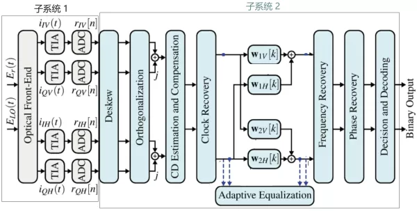
Of course, later, these CD/PMD effects were compensated through the receiver in the coherent system, via digital signal processing (DSP) algorithm processing and adaptive digital filtering, so DCM and other modules were no longer needed. This not only reduced insertion loss but also improved tolerance to nonlinear effects. Below, let us briefly look at the structure of a coherent receiver. A typical optical receiver of a digital coherent system consists of two main subsystems:

Among them: the first subsystem, shown in gray, is the receiver front end, mainly composed of the optical front end, transimpedance amplifier (TIA), and analog-to-digital converter (ADC). The second subsystem, shown in blue, consists of a series of digital signal processing (DSP) algorithms. The first DSP module is the deskew module, responsible for compensating for possible time mismatches during the alignment of the four receive components. The next module is the orthogonalization module, which compensates for receiver-front-end mismatches unrelated to time misalignment, such as slightly imbalanced photodetectors or power splitters. Then there are two static filters performing chromatic-dispersion compensation (CD). After that, there are the clock-recovery module, adaptive equalizer, frequency-recovery/phase-recovery, and so on. The specific functions of each module will not be discussed in detail here.
In our Knowledge Planet VIP community, we have shared quite a few documents on coherent technology, some of which are listed below:
- Homodyne coherent optical transmission.pdf
- Coherent optical communication technology.ppt
- PAM4 and coherent DSP optical chip market outlook.pdf
- Coherent optical communication technology based on digital signal processing.pdf
- Optical signal conditioning for coherent module testing.pdf
- Coherent optical communication.ppt
- Optical coherent modulation and demodulation research.pptx
- 400G digital coherent optical module.docx
Welcome to scan the code to join and download, and at the same time obtain more than 10,000+ other documents!
Also, a small job-seeking note: are there any positions related to optical fiber communication pre-sales? Welcome to leave a comment to let me know. Thank you!
Related Reading
- How to Understand the Performance of Coherent Network Solutions
- For Data Center 800G, PAM4 or Coherent Technology?
- Ciena’s 1.6Tb/s Coherent Optical Solution
Enjoy this article?
Subscribe to get new optical communication insights delivered to your inbox. Free, unsubscribe anytime.