Article source: ZTE Documents
The “light-speed road” of future communications – hollow-core fiber
In recent years, with the development of emerging technologies such as big data, cloud computing, and the Internet of Things, the demand for high-speed, large-capacity, low-loss optical communication systems has been increasing. Traditional glass-core fiber, which uses glass as the core material, has intrinsic limits, including capacity bottlenecks and performance limits.
For example, constrained by the channel bandwidth of the glass material, there is an upper limit to the amount of information it can transmit, just as the water flow in a pipe is limited. Moreover, since nonlinearity, attenuation, and latency all have theoretical limits, optical signals transmitted in glass fiber may become distorted, weakened, or slowed, which limits further improvement of transmission performance (such as distance and latency).
To overcome the problems of traditional fiber during transmission and improve the efficiency and performance of optical communication, hollow-core fiber came into being.
What Is Hollow-Core Fiber
Hollow-core fiber, abbreviated as HCF (Hollow-core fiber), uses air as the transmission medium, replacing the traditional fiber that uses “glass core” as the transmission medium.
Like traditional glass-core fiber, hollow-core fiber consists of three parts: the core, the cladding, and the coating. The main differences lie in the core and the cladding.
The core of hollow-core fiber is air, and the cladding is based on a microstructure design, usually composed of a series of tiny air holes. These air holes are arranged along the length of the fiber to form a specific periodic structure, and the cross-section of the cladding resembles a honeycomb made of a fine silicon mesh.

Schematic diagram of hollow-core fiber structure
How Hollow-Core Fiber Works
- Traditional fiber transmits light in the glass core based on the principle of total internal reflection.
When light enters the center of the fiber and propagates, the refractive index n1 of the fiber core is higher than that of the cladding n2, and the loss of the core is lower than that of the cladding. Thus, total internal reflection occurs, and the light energy is mainly transmitted within the core. Through successive total internal reflections, light can be transmitted from one end to the other.

Working principle diagram of traditional fiber
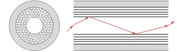
- The core of hollow-core fiber is air. Since the refractive index of air is smaller than that of the cladding medium, the condition for total internal reflection is not satisfied. Therefore, to transmit light in the hollow core, a specially designed cladding structure is required.
For example, in hollow-core photonic crystal fiber based on the photonic bandgap effect, its cladding is composed of a series of tiny air holes with precisely set hole sizes, hole spacing, and periodicity, while the core is air. When light is incident on the interface between the core and the cladding, it is strongly scattered by the periodically arranged air holes in the cladding. This multiple scattering produces coherence, so that light waves satisfying specific wavelengths and incident angles can return to the core and continue propagating.
Using this structure, light can be guided and propagated even when the refractive index of the core is smaller than that of the cladding.

Working principle diagram of hollow-core fiber
The photonic bandgap guiding mechanism above is a complex optical phenomenon, but we can try to explain it in plain language:
Imagine a long corridor with many pillars, arranged according to a certain rule, and you try to throw a ball to see how it rolls in the corridor.
Because of the pillars, the ball will not pass directly through the corridor, but will bounce and roll between the pillars. In some cases, the ball may be unable to move forward because of the arrangement of the pillars, as if it were “trapped”.
In the photonic bandgap guiding mechanism, the photon is like that ball, and the photonic crystal (a structure with periodic changes in refractive index) is like that corridor with many pillars. The air holes in the photonic crystal are like pillars, arranged according to a certain rule.
When light waves enter this structure, they are reflected and scattered between the air holes, just as the ball bounces between the pillars. Some frequencies of light cannot propagate in the cladding because of this special arrangement, just as the ball cannot move forward in some cases. These light waves are confined to propagate in the core, just as the ball is “trapped” in a certain region of the corridor.
What Are the Advantages of Hollow-Core Fiber
Compared with the currently widely used glass-core fiber, hollow-core fiber has significant advantages in the following aspects:
1 Low latency: The low refractive index of the internal air core and the optimized structural design make light propagate faster in hollow-core fiber, with latency dropping from 5us/km to 3.46us/km, a 30% reduction in transmission latency compared with existing fiber systems. This is very important for current and future latency-sensitive services. 2 Ultra-low nonlinearity: In the air core, the interaction between light and the medium is weakened, reducing the generation of nonlinear effects. The nonlinear effect of hollow-core fiber is 3 to 4 orders of magnitude lower than that of conventional glass-core fiber, allowing the input optical power to be greatly increased, thereby extending the transmission distance. Various equipment vendors in the industry, including ZTE, have carried out related optical system research based on this characteristic, such as 128QAM high-order modulation and high-power amplifier technologies, which are expected to increase system capacity and transmission distance by at least 2 times. 3 Potentially ultra-low loss: Currently, hollow-core fiber can achieve a loss of 0.174dB/km, on par with the performance of the latest generation of glass-core fiber. At the same time, the theoretical minimum limit of hollow-core fiber in the communication window can be as low as below 0.1dB/km, smaller than the theoretical limit of 0.14dB/km for ordinary glass-core fiber. 4 Ultra-wide operating band: With continuous optimization of hollow-core fiber structure design, an ultra-wide band exceeding 1000nm can be provided, easily supporting the O, S, E, C, L, U bands.
What Are the Application Scenarios of Hollow-Core Fiber
So, in what areas will hollow-core fiber be applied?
| Application Field | Specific Application | Description |
|---|---|---|
| Long-distance communication | Cross-border communication, submarine cable, satellite communication | With high efficiency, high speed and large capacity, hollow-core fiber is the preferred solution for future long-distance communication |
| Data center and cloud computing | Data transmission | The high bandwidth and low loss of hollow-core fiber make it an ideal choice for data center and cloud computing |
| Medical field | Medical equipment manufacturing | Hollow-core fiber can be used to manufacture medical equipment, providing clearer and more accurate images |
| Industrial field | Sensor and monitoring system construction | Hollow-core fiber can be used to build sensors and monitoring systems for real-time monitoring and remote control of industrial equipment |
| Other fields | Secure communication construction | Hollow-core fiber can be used to build secure communication, improving communication security and reliability |
In short, as a new type of communication technology, hollow-core fiber has broad application prospects and great development potential. It will bring revolutionary changes to the future communication field. Let us look forward to that day together!
Related Reading
- Hollow-Core Fiber – What Is Photonic Bandgap Fiber?
- Hollow-Core Fiber 6: Nested and Non-Nested ANF Hollow-Core Fibers
- Hollow-Core Fiber 7: How to Reduce Surface Mode Loss?
Enjoy this article?
Subscribe to get new optical communication insights delivered to your inbox. Free, unsubscribe anytime.