In optical fiber connection technology, to keep loss low, the connection must be made with precision. This precision requirement is usually called “tolerance”. Simply put, “tolerance” is the maximum allowable deviation when fibers are mated. For example, position misalignment (lateral offset), angle deviation, and so on.
The size of these tolerances directly determines whether light can be efficiently transferred from the core of one fiber to the core of another.
For multimode fiber systems, because of the large core area and multimode transmission characteristics, the tolerance is relatively loose. When the core diameter and numerical aperture of the receiving fiber are not smaller than those of the transmitting fiber, efficient power transfer can be achieved, but reverse transmission may produce significant loss due to brightness reduction.

It is worth noting that when the core diameter of the receiving fiber is slightly larger than that of the transmitting fiber, it may seem favorable for coupling, but it actually causes complex mode field distortion. This manifests as the guided modes of the input fiber being unable to fully convert into the guided modes of the receiving fiber, causing part of the energy to leak into the cladding.
For single-mode fiber, efficient coupling requires that the fundamental mode field distributions (especially the effective mode field area) of the two fibers be highly consistent, and it is extremely sensitive to both lateral offset and angle deviation.
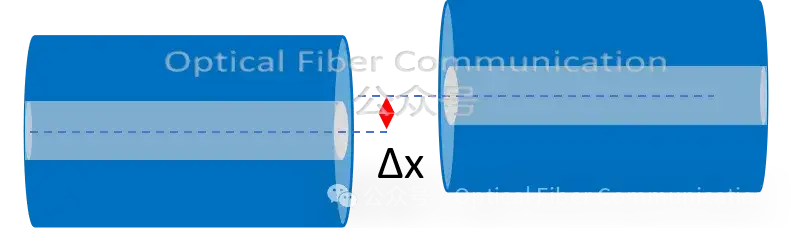
The loss caused by lateral offset of the core is called offset loss (or lateral displacement loss), which is the main source of insertion loss in fiber connections, especially significant for single-mode fiber.
The figure below shows a schematic of lateral displacement (offset) when two single-mode fibers are coupled:
Without considering other factors, the connection loss caused by lateral offset of the fiber can be approximately calculated as follows:

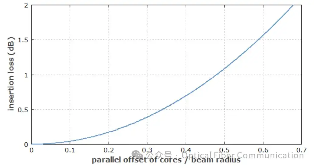
The chart below quantitatively shows the offset loss caused by parallel core offset (lateral misalignment) at a single-mode fiber mechanical splice.
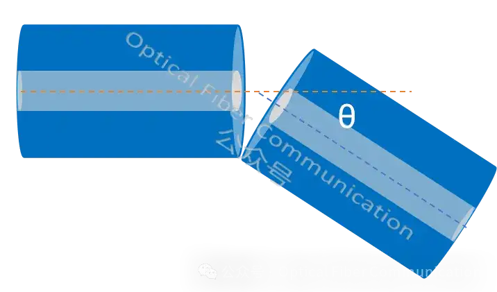
Angle deviation refers to when two fibers are mated, if their end faces are not completely parallel (that is, the axes of the fibers are not coincident but form an angle), causing part of the light to be unable to effectively transfer from one fiber to the other, resulting in signal energy loss.
The following is a schematic diagram of angle deviation:
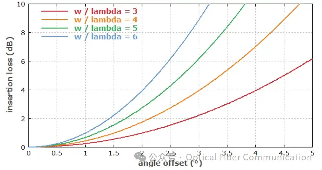
The loss caused by angle deviation Delta-theta follows an exponential decay law:
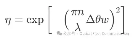
Here n is the refractive index of the material outside the fiber, and w is the mode field diameter. This formula shows that fibers with a large mode field diameter are more sensitive to angular tolerance: when the mode field diameter w or the operating wavelength lambda increases, the loss caused by the same angle deviation grows geometrically.
The figure below shows the loss at the mechanical splice of single-mode fibers with different mode field diameters (or the ratio of mode field diameter to wavelength, w/lambda) under different angle deviations.
Another important source of coupling loss is mode field diameter (MFD) mismatch. The mode field diameter is defined as the distance between the two points where the light intensity distribution drops to 1/e² of its maximum value on the axis (center). MFD is closely related to the operating wavelength and usually increases with wavelength.
For example, the typical MFD value of single-mode fiber at 1310nm is 9.2±0.5um, while at 1550nm it is 10.5±1.0um.
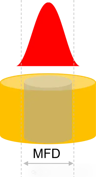
It needs to be emphasized here that MFD is not the physical diameter of the core; it characterizes the actual distribution range of light energy in the fiber, which is especially important for single-mode fiber. When the mode field diameters of the two mated fibers are exactly equal (MFD1 = MFD2), the optical field mode output by the transmitting fiber can be ideally (or efficiently) coupled into the mode field region of the receiving fiber.
When the mode field diameter of the transmitting fiber is larger than that of the receiving fiber (MFD1 > MFD2), the larger optical field output by the transmitting fiber tries to enter the smaller effective receiving region of the receiving fiber, resulting in coupling loss.
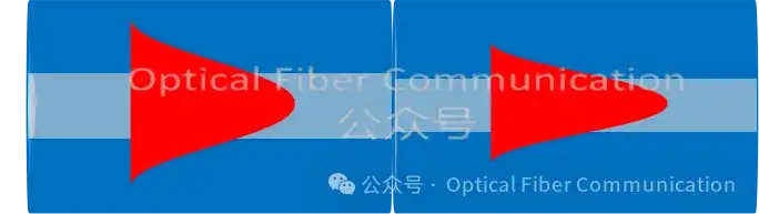
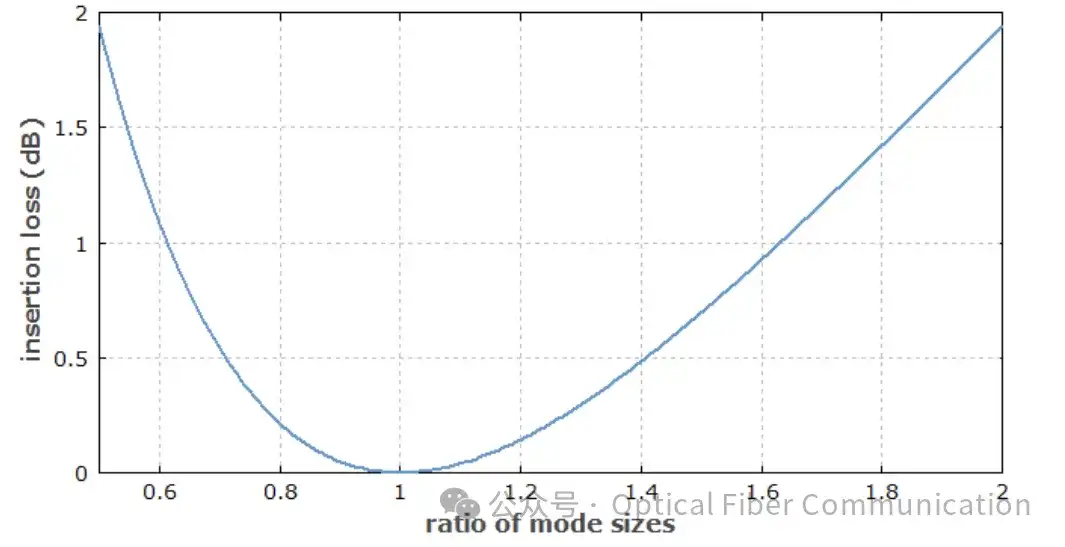
The magnitude of the coupling loss depends on the degree of difference between the two mode field diameters. The greater the difference, the greater the loss. There is a basic formula to calculate this loss (in dB):
Loss about -10 * log10[ (4 * (MFD1/MFD2 + MFD2/MFD1)^-2) ]
The figure below shows the insertion loss produced at a single-mode fiber mechanical splice due to mode field diameter (MFD) mismatch.
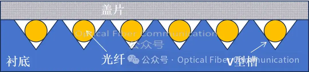
Therefore, in engineering practice, to achieve efficient coupling, fiber alignment adjustment techniques are usually used. Typical direct alignment methods include the V-groove method and the three-rod method.
The following is a schematic diagram of a multi-fiber V-groove structure:
Thanks for reading. If there are any inaccurate expressions, please point them out~
We can provide AOC/DAC/MPO cables, optical modules, and optical transceivers at various rates, as well as various optical components used in them, such as aspheric lenses, collimating lenses, aspheric lens arrays, waveplates, etc., and can also provide custom development services.
Welcome to contact market@bitwax.com
Related Reading
- Fiber Coupling: Five Questions and Answers from NA and MFD to Mode Matching
- An Innovative CPO Fiber Vertical Coupling Scheme
- What Is the Propagation Path of Light in Optical Fiber?
Enjoy this article?
Subscribe to get new optical communication insights delivered to your inbox. Free, unsubscribe anytime.