
In optical fiber communication systems, repeater equipment (electrical repeaters or optical amplifiers) usually needs to be placed at certain intervals to compensate for the signal. In optical amplification schemes, the erbium-doped fiber amplifier (EDFA) is usually the most common gain medium amplifier. But today we are going to talk about another type of optical amplifier: ROPA, the remote optically pumped amplifier. What is different about it?
Before getting into the topic, let us first understand the EDFA.
What Is an EDFA?
EDFA, fully known as Erbium-Doped Fiber Amplifier. Its working principle is to dope erbium ions inside the fiber, then use a laser of a specific wavelength as the pump source, causing the erbium ions to transition from a lower energy state to a higher state, thereby absorbing the energy of the pump light and releasing it when the signal light passes through, achieving signal amplification.

Figure: Schematic diagram of an EDFA
Let me emphasize here: an EDFA transmits the pump source and the signal light together in the same fiber or at relatively close positions. In other words, the entire EDFA device is usually inserted on the same equipment, suitable for transmission distances that are not too long.
However, in some information transmission scenarios with complex geographical and environmental conditions, inconvenient power supply, and long communication distances, such as continuous high mountains, vast seabeds, and uninhabited deserts, the installation and maintenance of ordinary EDFAs are inconvenient. At this time, the remote optically pumped amplifier (ROPA) comes in handy.
What Is a ROPA?
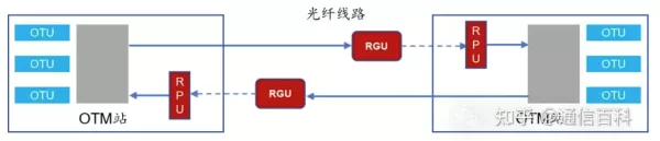
Remote pumping, in English Remote Optical Pumping Amplifier, is essentially a remote optical amplifier subsystem composed of two parts: the pump unit (RPU) and the remote gain unit (RGU).

Figure: Position of ROPA in the optical system
Among them, the pump source unit RPU is usually inserted in the subrack of the site in the form of a single board. The remote gain unit RGU mainly provides the gain medium, that is, erbium-doped fiber (EDF), for the line. As a passive device, it requires no power supply. It is packaged through an optical cable splice box and connected into the fiber link. In some cases, the RGU also has a gain flattening filter to improve gain flatness, reduce noise figure, and improve system transmission performance.
Because the pump unit and the gain unit are physically separated, it satisfies optical repeater applications where power supply and monitoring conditions are unavailable.
ROPA Structure and Principle
The internal composition of the remote pump amplifier is shown in the figure below:

Figure: Schematic diagram of ROPA structure
The circulator in the figure is used to block the leakage of amplified noise into the downstream fiber transmission link, and the optical filter is used to eliminate the influence of reflected signals on the pump light source and filter out noise around the signal light.
In the selection of the pump light source, there are two types of pump light suitable for fiber systems: 980nm and 1480nm. So which one should be used?
Two aspects are mainly considered: one is the transmission loss of the fiber, and the other is the frequency-shift gain effect of Raman amplification. I will not say much about the fiber loss, as shown in the figure below:

Figure: Fiber loss window diagram
Obviously, to make the pump light travel farther, the 1480nm pump light is our first choice. In addition, 1480nm light, after Raman frequency shift, becomes light in the 1550nm band, which also fits the transmission window of WDM systems.
Next, let us talk about the principle of ROPA amplification: We know that erbium ions have three energy levels for optical amplification: the excited state, the metastable state, and the ground state. When irradiated with 1480nm pump light, Er ions transition directly from the ground state to the metastable state, forming a population inversion. When signal light enters, if the photon energy of the signal light equals the difference between energy levels E2 and E1, then when the erbium ions at energy level E2 return to the ground state E1, a large number of photons exactly identical to themselves are produced. At this time, the signal photons transmitted through the erbium-doped fiber rapidly increase, producing signal amplification, so that the signal light is amplified and gains gain.

Figure: Er ion energy level diagram
Applications of ROPA
In applications, depending on whether the signal light and pump light share the same fiber, ROPA can be divided into two types:
- ROPA co-path transmission system

In the co-path system, the pump light and signal light are transmitted in the same fiber. Besides the EDF amplification in the remote RGU, the pump light also provides a certain Raman amplification effect on the transmitted signal.
- ROPA bypass transmission system

Compared with the co-path ROPA system, since the pump light and signal light are on different fibers in the bypass system, there is no Raman amplification effect. However, using the bypass remote pump approach has one advantage: there is no interaction between pump and signal, which helps improve the effective transmission distance of high-power pump light.
There is also a scheme that mixes the above two systems, that is, dual pumping, where one pump light is transmitted in the same fiber as the signal light and the second pump light is transmitted in a different fiber from the signal light. This scheme is used relatively rarely.
It should be noted that although ROPA systems perform very well in special scenarios, they have relatively high requirements for the fiber. Generally, there should be no connectors within 20 km of the RPU or the ODF rack, and all splice points should use fusion splicing as much as possible. Otherwise, not only will the amplifier gain fail to be achieved, but the fiber, optical connectors, and even RPU devices may be burned.
Related Reading
- What Is the Propagation Path of Light in Optical Fiber?
- Optical Fiber Communication: The Structure of Optical Fiber
- Optical Fiber Communication: Mode Field Diameter and Cutoff Wavelength
Enjoy this article?
Subscribe to get new optical communication insights delivered to your inbox. Free, unsubscribe anytime.