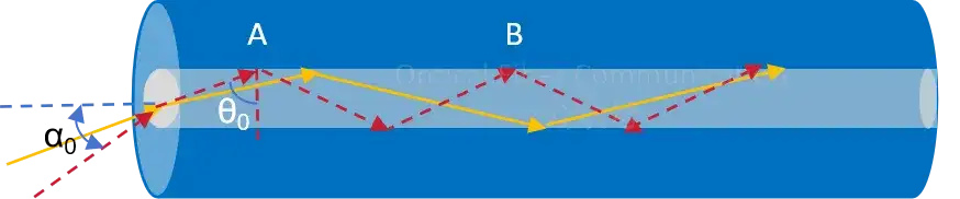
In optical fiber communication, the propagation of light depends on the refractive index difference between the core and the cladding.
That is, when light is incident from the core onto the interface, if the incident angle is greater than the critical angle theta0, total internal reflection occurs, and no light energy transmits into the cladding to leak out. This is the light-guiding principle of optical fiber.
Reflected on the fiber end face, light at the fiber end face can only propagate in the fiber by total internal reflection when its incident angle is smaller than the acceptance angle alpha0 of the fiber.
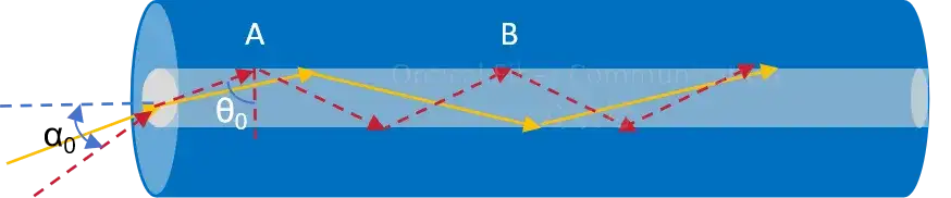
This acceptance angle is what we call the numerical aperture NA of the fiber:

Here n_core represents the refractive index of the core, and n_cladding represents the refractive index of the cladding.
That is, the numerical aperture is related to the refractive index distribution of the fiber, reflecting the ability of the fiber to receive light. For step-index fiber and graded-index fiber, the refractive index distributions are as follows:
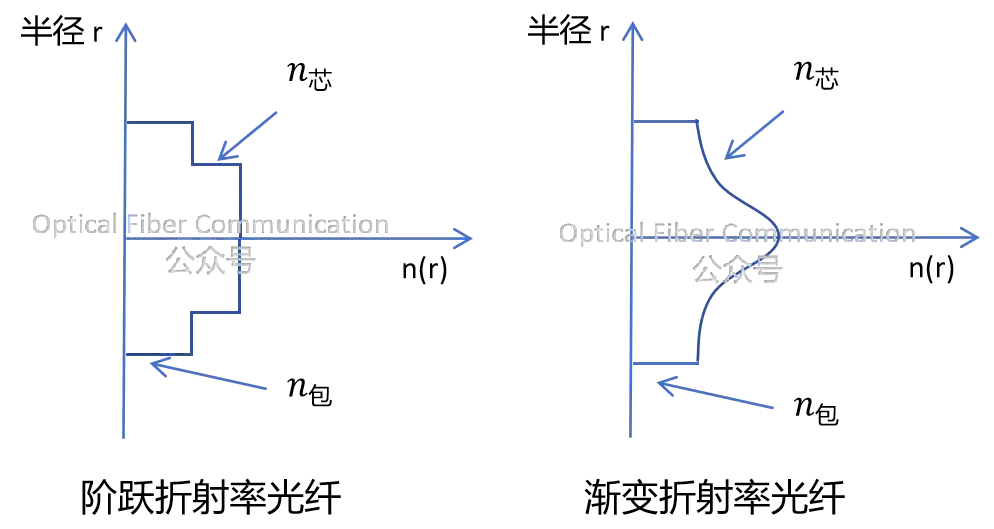
From the refractive index distribution diagram above, it can be seen that for step-index fiber, since the refractive indices of the core and cladding can be regarded as constant, the numerical aperture is the same at every point. For graded-index fiber, the numerical aperture is largest at the center point.
Perhaps most friends think that as long as the incident light is smaller than the acceptance angle, it can propagate in the fiber. In addition to NA, the standing-wave condition of waveguide constructive interference must also be satisfied.
What is the standing-wave condition?
In optical fiber, the standing-wave condition can be expressed as: light can propagate stably in the fiber only when the optical path difference formed between the two end faces of the fiber is an integer multiple of the optical wavelength. I simplify the standing-wave formula as follows; the original formula is somewhat complex.

We just need to know that only light at certain incident angles theta1, theta2, theta3…theta_m can propagate stably in the waveguide. These are what we call the modes of the fiber, corresponding to different mode numbers m.
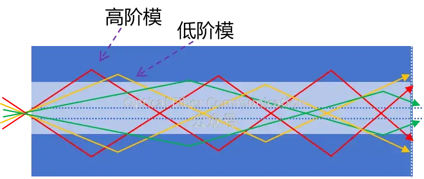
Here, the larger m is, the deeper the light enters the cladding and the faster the loss; moreover, higher-order modes propagate slower, while lower-order modes propagate faster.
From the above explanation, we already know that light transmitted in the fiber must satisfy both the total internal reflection condition and the standing-wave condition. Total internal reflection is related to the refractive index difference between the core and the cladding; the larger the refractive index difference, the larger the acceptance angle. The standing-wave condition is related to the core size; the larger the core, the more modes are allowed.
So to evaluate which modes the fiber can transmit, especially when we need to keep light propagating in single mode in the fiber, there are too many influencing factors, such as the physical size of the fiber, the refractive index difference, the frequency of the light wave, the incident angle, and so on.
For this reason, a normalized frequency V value was introduced, using only this one parameter to describe the structural characteristics of the fiber, which is much more convenient.


If our wavelength lambda is determined, V depends on the geometric radius r of the fiber and the refractive index difference. The smaller V is, the weaker the fiber’s ability to confine light leakage, and the fewer modes allowed to transmit. According to the formula, increasing the wavelength lambda or the refractive index of the cladding can reduce the V value, thereby reducing the number of propagating modes. Therefore, based on the Bessel function and fiber mode theory, a V value was derived: 2.405. This value is the boundary line of the number of fiber modes. As shown in the figure below, it represents the schematic relationship between several low-order linearly polarized modes and the normalized frequency V.
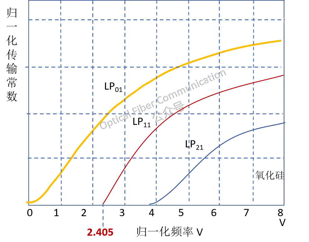
Here LP01 is the zeroth-order mode. It can be seen that it exists for all V values and is a mode that never cuts off, also called the fundamental mode. LP11 is the first-order mode, cutting off at V=2.405. Therefore, the above only allows the fundamental mode LP01 to transmit, that is:
- When V < 2.405, only one mode can propagate in the fiber, becoming single-mode fiber.
- When V > 2.405, higher-order modes will also propagate in the fiber, for example, few-mode fiber with a V value between 3 and 10.
Compared with multimode fiber, single-mode fiber has a much smaller core diameter and refractive index difference between the core and cladding. In addition, from the formula above, we can also derive another important formula, namely the cutoff wavelength:

When lambda < lambda_cutoff, the single-mode condition is no longer satisfied, and higher-order modes are produced, leading to increased transmission loss, and the single-mode fiber becomes multimode fiber. Therefore, for step-index fiber, the V value can be used to specify the condition for single-mode guidance.
However, to improve the light-guiding ability of the fiber and reduce bending-induced loss, it is generally recommended to set the V value as high as possible. From the V value formula above, increasing the core radius r or the core refractive index can both make V larger.
That is all for today. Finally, a small question: for hollow-core fiber and photonic bandgap fiber, does the V value of 2.405 exist? Everyone is welcome to leave comments and discuss! Thanks for reading!
Related Reading
- What Is the Propagation Path of Light in Optical Fiber?
- Optical Fiber Communication: The Structure of Optical Fiber
- Optical Fiber Communication: Mode Field Diameter and Cutoff Wavelength
Enjoy this article?
Subscribe to get new optical communication insights delivered to your inbox. Free, unsubscribe anytime.