
Recently I have been reading materials about CPO and LPO, and today I will briefly discuss them as a summary of my learning.
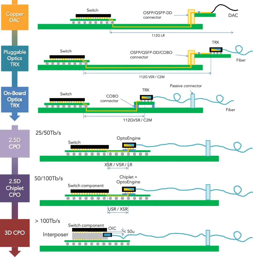
Traditional optical modules are independent of the switch chip and connected to other electronic components through copper cables or optical fiber. This approach tends to produce large power consumption and signal loss during high-speed signal transmission.
In addition, network rates such as DCI are gradually developing from 400G to 800G, and even 1.6T, and in the near future may reach 3.2T. As the rate increases, the power consumption of a single optical module also rises sharply, causing the overall system power consumption to increase greatly.
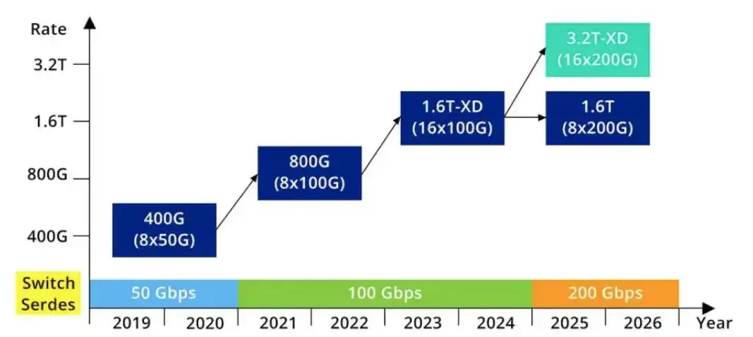
Figure 1 – Data center interconnect rate roadmap
The power consumption of an SFP module is about 2W, 100G optical modules are generally 1.5W to 3W, 400G QSFP-DD DR4 optical modules can be controlled within about 12W, and 800G optical modules fluctuate between 12W and 16W.
At the same time, let us analyze from the perspective of device packaging. During device packaging, when the signal rate doubles from 56Gbd to 112Gb/s, for a given length of low-loss PCB trace, even if we use advanced PCB materials, the insertion loss will roughly double.
Generally speaking, the shorter the electrical channel and the fewer intermediate conversions (vias, connectors), the easier it is to manage signal integrity issues. This drives moving optical devices inward, as close to the ASIC as possible, thereby effectively reducing power consumption. Based on this, two main solutions have emerged:
- CPO: Co-Packaged Optics, optoelectronic co-packaged module;
- LPO: Linear-drive Pluggable Optics, linear-drive pluggable module.
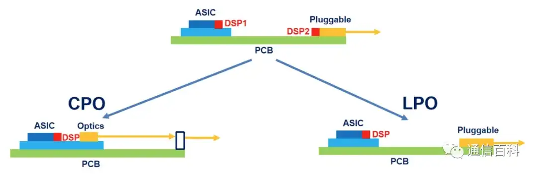
Figure 2 – From pluggable to CPO and LPO
What Is CPO?
What Is LPO Technology
LPO, linear-drive pluggable optics, is an optical module packaging technology. Whether CPO or LPO, one of the main goals relative to traditional optical modules is to reduce power consumption, and the power consumption of the DSP accounts for the highest proportion in the entire module.
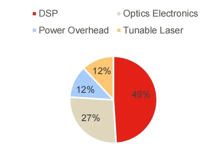
Figure 10 – Power consumption distribution of a 400 ZR optical module
Therefore, for LPO, its direct characterization lies in removing the DSP, using only linear analog components in the data link, with no CDR or DSP in the design. By using transimpedance amplifiers (TIA) and driver chips (DRIVER) with excellent linearity and equalization capability to replace the DSP.
ODCC released the 112G LPO Optical Module Application White Paper in 2023, which involves the design of LPO modules. Its block diagram is as follows:
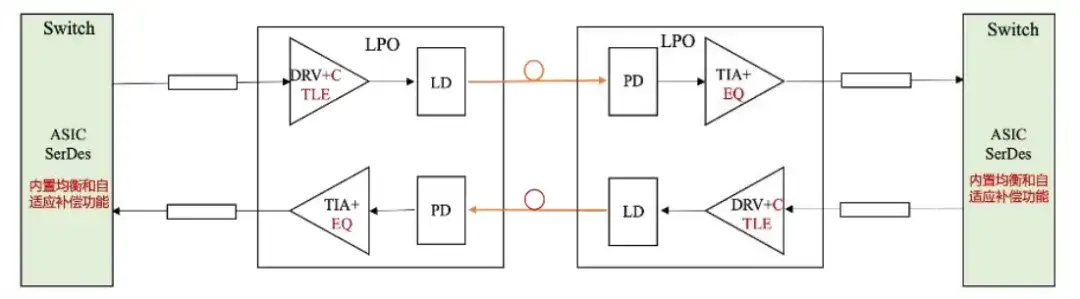
Figure 11 – Design block diagram of an LPO module
- Remove re-timer components such as CDR/oDSP;
- Use DRV/TIA electrical chips with better performance and stronger SI compensation capability;
- Integrate part of the compensation function into the network device ASIC chip;
- The signal regeneration and digital signal compensation functions originally implemented by oDSP are instead segmented-compensated through the network device ASIC chip, DRV, and TIA.
It should be noted that this is somewhat different from CPO. LPO’s removal of the DSP really means not wanting to implement the DSP in the electrical chip inside the optical module, but instead placing the DSP function on the system device side. The figure below more intuitively shows the similarities and differences between the traditional DSP/Retiming-based solution and the LPO solution.
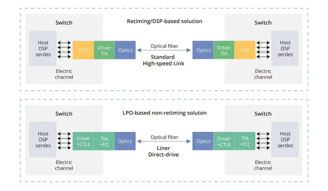
Figure 12 – Comparison between the LPO solution and the DSP-containing solution
In terms of interface, LPO has no requirements for the packaging of the module itself. Whether it is QSFP, QSFP-DD, or OSFP, OSFP-XD, etc., the LPO solution can be implemented.
In the industry, electrical chip vendors that are relatively weak in the DSP field, such as Macom, Semtech, and Maxim, are strongly promoting LPO. The main reason is to bypass the DSP shortcoming through the LPO solution. At present, LPO standardization is not yet mature, mainly involving electrical interfaces and optical interfaces.
Among them, the electrical interface is mainly OIF’s CEI-112G-Linear-PAM4 protocol. It is understood that, as of the last update (April 2024), the CEI-112G-Linear-PAM4 standard has made substantial progress and has been adopted and implemented by the industry, at least at the product level with companies such as Hisense having launched 800G linear interconnect cables based on this standard.
In terms of optical interfaces, the IEEE 802.3 series protocols are mature and universal standards, and Retime-type pluggable optical modules must comply with these protocols. If compliance with the 802.3 protocol can be achieved, LPO can achieve the greatest degree of “interconnection and interoperability”.
Differences Between CPO and LPO
Both CPO and LPO are still evolving. CPO packaging and LPO packaging each have their own characteristics and advantages. CPO packaging technology focuses on optoelectronic co-packaging and is suitable for high-speed, high-density interconnect transmission scenarios; while LPO packaging technology focuses on pluggability and cost-effectiveness, suitable for short-distance transmission scenarios.
Within the CPO framework, if a system device fails, the power needs to be turned off and the entire board replaced, which is quite inconvenient for maintenance tasks. In contrast, the pluggability of LPO optical modules enables efficient replacement without shutting down the entire system, further improving the overall convenience of the LPO solution and simplifying fiber cabling and equipment maintenance processes.
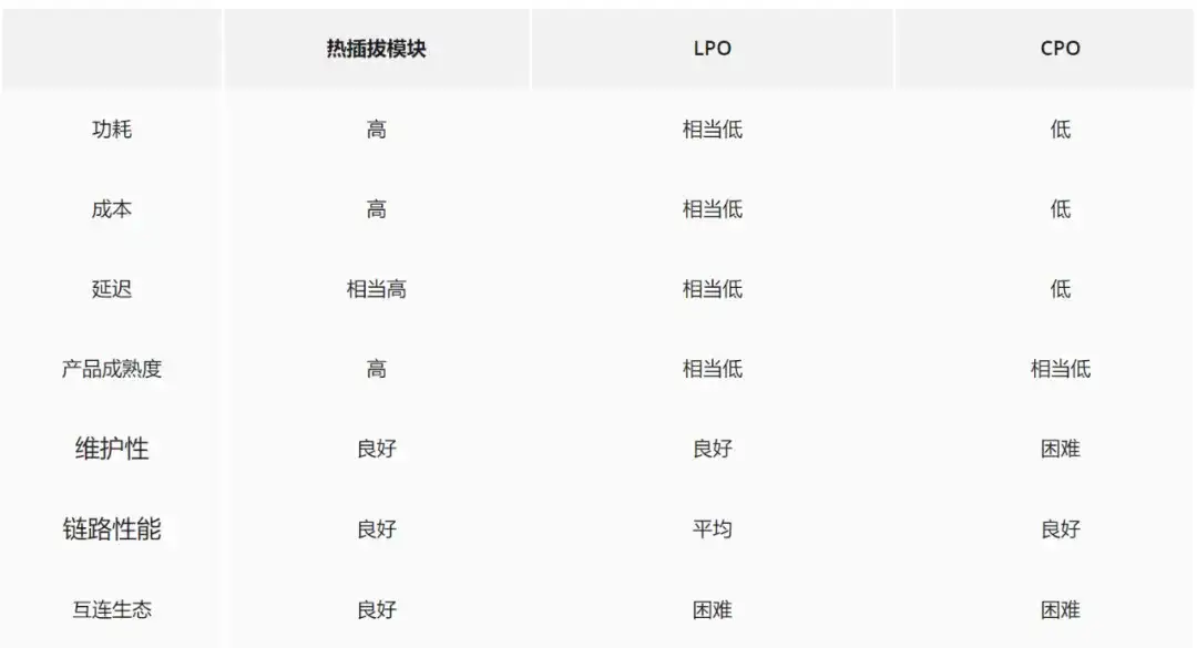
Figure 13 – Comparison of several solutions
Overall, LPO is a technical route evolving downward from pluggable optical modules, easier to implement and more certain than the CPO solution.
However, according to some experts, LPO technology brings important design problems to the electrical channel on the system side. Currently the mainstream SerDes specification is 112G, which will soon be upgraded to 224G. Experts believe that LPO technology cannot meet the requirements of 224G SerDes.
Related Reading
- LPO, CPO, and the 1.6T / 3.2T Optical Module Market
- Some Viewpoints on “Modulator and LPO/CPO”
- About LPO MSA, Do You Know These Questions?
Enjoy this article?
Subscribe to get new optical communication insights delivered to your inbox. Free, unsubscribe anytime.