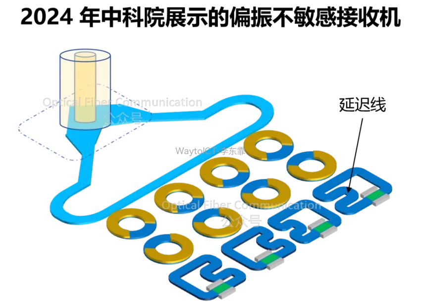
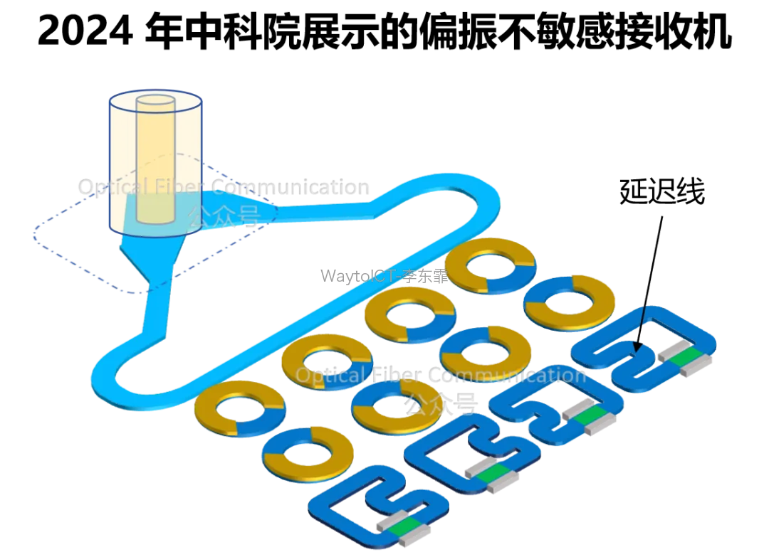
In the article “Passive and Active Polarization Management, Intel’s Silicon Photonics Polarization Diversity Receiving Scheme“, I mentioned the receiver structure demonstrated by the Chinese Academy of Sciences.
There was a “delay line” marked in it, and a reader privately asked me about its working principle. Let me explain it in detail here.
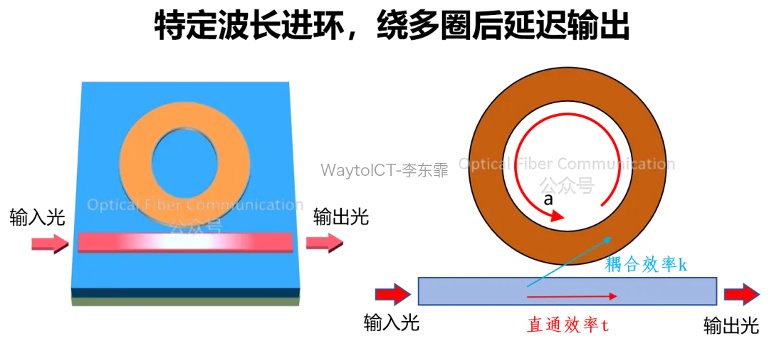
The function of a delay line is to apply a time delay to the optical signal. To achieve delay, the most intuitive scheme is to let light of a specific wavelength travel a longer optical path.
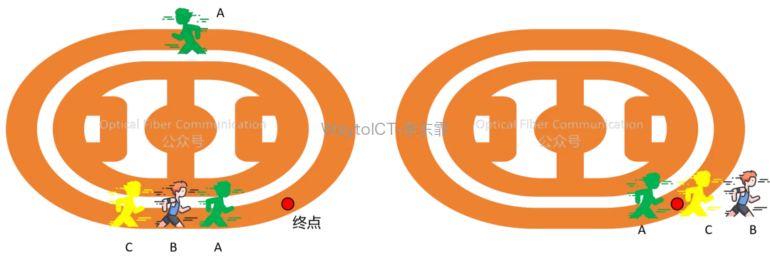
The microring is a very common structure in such applications, mainly using the slow-light effect. When the incident light wavelength matches the resonant wavelength of the microring, the light circulates multiple times inside the ring waveguide, thereby producing group delay.
For example, in a running training session of groups A, B, and C, normally the training ends when C reaches the finish line, but because the little green person got excited (just a metaphor) and ran an extra lap, the entire group’s (group delay) training end time was pushed back.
In the resonant state, the wavelength that can enter the microring is determined by the resonance condition. The resonance and anti-resonance formulas below have been introduced in several of our previous articles, so I will not repeat them here.
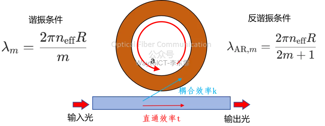
The transmission performance of the microring is mainly determined by the coupling coefficient, the through efficiency, and the microring radius.
A microring optical delay line based on the resonance principle can adjust the group delay through the resonance condition. For example, by changing the effective refractive index of the microring, its resonant wavelength can be adjusted, thereby controlling the delay magnitude.
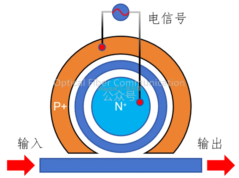
The delay adjustment range of a single microring is limited. We can connect multiple microrings in series through a bus waveguide. In this structure, multiple microrings are cascaded in sequence along the bus waveguide, and light propagates unidirectionally along the bus, passing through the coupling region of each microring in turn.
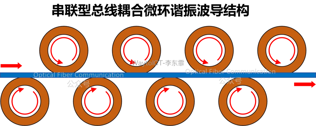
Light of a specific wavelength satisfying the resonance condition is efficiently coupled into the ring, and after accumulating multiple resonance circulations in the ring, is coupled back to the bus for output.
Another structure directly connects multiple microrings in series: light enters the first ring, travels one cycle, and then couples into the second ring, and so on, passing through all microrings in sequence to form a resonant cavity with a longer equivalent length.
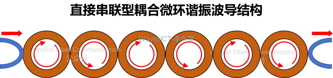
This type of resonance-based microring optical delay line has the advantages of small size and low power consumption, but its operating bandwidth is narrow, and multi-stage microring cascading also brings greater delay jitter.
At the same time, precisely controlling the coupling coefficient and resonant wavelength of each microring is also relatively complex to implement.
Therefore, there is another scheme, which uses the anti-resonance principle to make the microring operate near the anti-resonance wavelength.
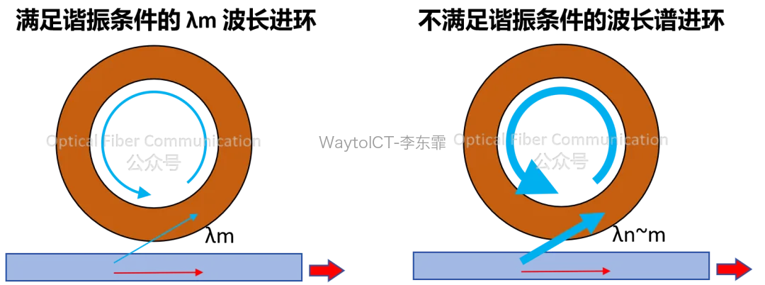
Simply put, in the anti-resonance state, except for the resonant-point wavelength, all other wavelengths have a portion of light entering the microring, which is clearly different from the resonance state where only specific wavelengths can efficiently enter the ring.
In this way, we can control the delay by adjusting the coupling efficiency: the delay is smallest when the coupling efficiency approaches 0, and largest when the coupling efficiency approaches 1.
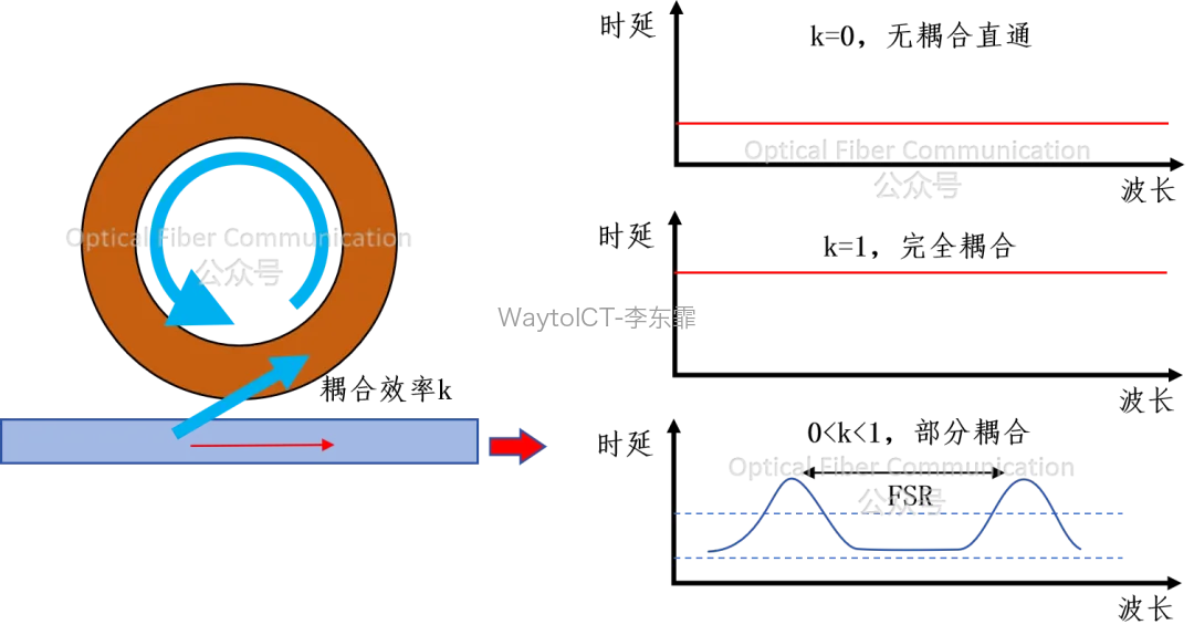
The delay of an anti-resonance microring is mainly determined by the coupling efficiency and is insensitive to changes in the resonant wavelength, so the operating state is more stable.
Besides microring-type optical delay lines, there are also Bragg grating delay lines, which rely on the periodic structure of the grating to produce the slow-light effect and achieve signal delay. For the principle of gratings, refer to “What Is a Fiber Bragg Grating Like?“.
Next time we will talk about this scheme.
Related reading:
STMicroelectronics: Progress of Silicon Photonics Process Platform Supporting NPO/CPO
Broadcom: 400G EML Evolution Roadmap and Differential Drive Scheme
You can add WeChat WaytoICT to be invited to join the Semiconductor & Optical Components Industry Chain Group 2.
Welcome to join our community to obtain high-value technical documents, trend research reports, and various supply-demand business opportunities in the fields of semiconductor chips / optical components / optical modules.
If you are interested in semiconductors / optical components / optical modules / optical fiber communication, welcome to follow us!
Enjoy this article?
Subscribe to get new optical communication insights delivered to your inbox. Free, unsubscribe anytime.