This article is sourced from the “ODCC-2024 AI Network Optical Switch Technical Report”; the download method is provided at the end of the article!
The optical switch is responsible for establishing and breaking connections between fibers. High-performance optical switching can achieve millisecond-level or faster switching speeds, which is crucial for meeting the dynamic traffic demands of data centers.
Depending on the implementation technology, optical switching can generally be divided into 3D MEMS (Micro-Electro-Mechanical System) technology, digital liquid crystal DLC (Digital Liquid Crystal) technology, and direct light beam steering DLBS (Direct Light Beam Steering) technology.
The main performance indicators of optical switching include:
- Switching speed: Switching speed is an important performance indicator of optical switching, directly affecting the dynamic response capability of the data center network. High-performance optical switching should have millisecond-level switching speed to meet high-frequency traffic change requirements.
- Insertion loss: Insertion loss is the power loss of the optical signal when it passes through the optical switch. Lower insertion loss helps improve signal quality and transmission distance.
- Return loss: Return loss is the ratio of the incident optical power to the reflected optical power when the optical signal passes through the optical switch. Higher return loss helps reduce signal reflection and interference. Return loss video introduction:
Science Popularization Alliance, Liked 5
- Durability and reliability: The durability and reliability of optical switching are key to ensuring the stable operation of the data center network. High-performance optical switching should have a long service life and a low failure rate.
1. 3D MEMS Optical Switching
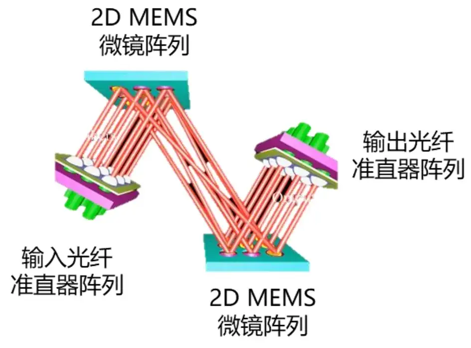
The MEMS optical switch consists of an input fiber collimator array (FAU: Fiber array unit), an input MEMS micromirror array, an output MEMS micromirror array, an output fiber collimator array, and the supporting drive and control hardware and software. The input and output MEMS micromirror units are two-dimensional dual-axis reflective micromirror arrays, and two MEMS micromirror arrays form an N*N matrix switch array. The structure is shown below:
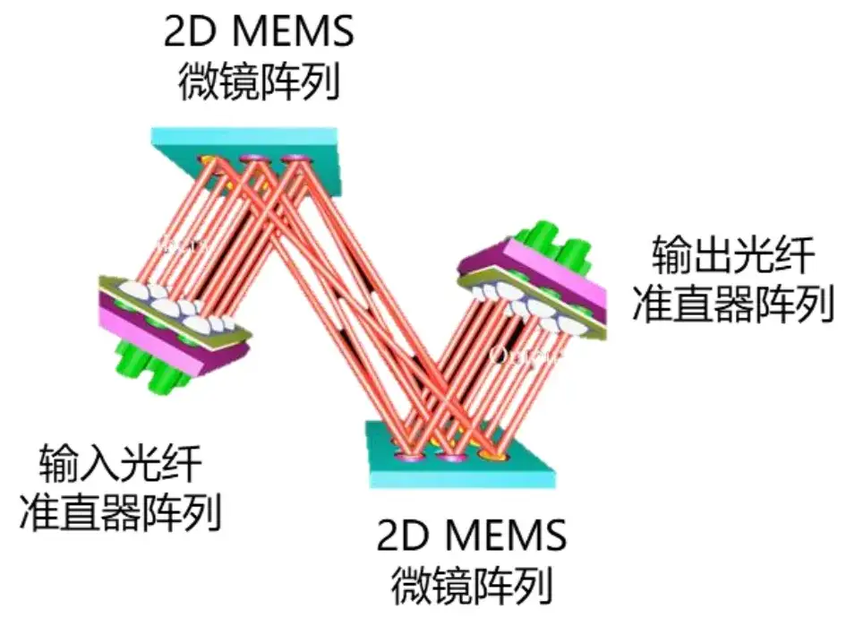
The input optical signal passes through the fiber array and enters the corresponding micromirror unit of the MEMS micromirror array in sequence at a certain angle. Each micromirror unit has independent drive control, and the required rotation angle is achieved by applying different electrical signals. The input MEMS micromirror array steers the incident signal to the corresponding micromirror unit of the target output micromirror array by adjusting the rotation angle of the micromirror unit, completing routing or cross-connection. The output micromirror array is responsible for deflecting the optical signal so that it is normally incident on the corresponding port of the output fiber collimator array, achieving the best coupling output and optimal switching insertion loss.
The MEMS micromirror array is fabricated by semiconductor processes. The MEMS micromirror unit consists of a reflective mirror, a drive structure, and electrical interconnects. The mirror diameter is about several hundred microns. The drive structure drives the MEMS mirror to achieve two-dimensional deflection, thereby realizing the optical path deflection function. Common drive methods include magnetoelectric drive, electrostatic comb drive, and thermoelectric drive. Magnetoelectric drive uses the Lorentz working principle: when current passes through the coil of the micromirror unit, the magnetic field generates a Lorentz force to drive the mirror rotation. It has a low drive voltage and good linearity, but requires a magnet array and relatively complex packaging.
In addition, since the coil needs to be energized during driving, and different rotation angles correspond to different currents, heating and temperature drift problems are likely to occur. Thermoelectric drive changes the temperature of the micromirror drive arm; the different thermal expansion coefficients of different materials in the drive arm cause the micromirror to deflect. The drive arm has a high temperature and easily deforms under stress, with higher power consumption, slower response speed, and poor angle accuracy. Usually MEMS micromirrors use electrostatic drive: a voltage is applied between the fixed comb and the movable comb of the vertical comb structure, and under the electrostatic force between the interleaved combs the movable comb displaces, driving the mirror to rotate. Different bias voltages produce different deflection angles of the mirror, as shown below.
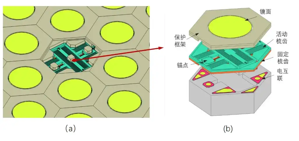
Figure MEMS optical switching: (a) micromirror array schematic, (b) element composition and principle schematic
2. Digital Liquid Crystal Technology DLC Optical Switching
Liquid crystal is a phase state of matter whose properties lie between solid and liquid. Liquid crystal material has both the fluidity of a liquid and the long-range order of a crystal in the arrangement of its molecules, forming an intermediate state that has part of the properties of both crystal and liquid. The orderliness and anisotropy in the arrangement of liquid crystal molecules give liquid crystal material physical properties such as refractive index anisotropy and dielectric constant anisotropy, just like crystal material. When a voltage is applied across the two ends of a liquid crystal cell, the liquid crystal molecules deflect, causing the birefringence of the liquid crystal to change and producing a phase delay — this phenomenon is the electro-optic effect of liquid crystal. Using this property, an LCLM (liquid crystal light module) can be realized: under external electric field modulation, the polarization state of the incident light rotates as it passes through the liquid crystal cell. The digital liquid crystal optical switching system uses the cascade of the liquid crystal electro-optic effect and crystal optical wedges, and can arbitrarily route the input light of N ports to N output ports, completing the N × N liquid crystal optical switch function. Digital liquid crystal optical switching uses the cascade of the liquid crystal electro-optic effect and crystal optical wedges to produce beam deflection, and can arbitrarily switch the input light of N ports to any N output ports, completing the N × N liquid crystal optical switching function.
The composition and key component functions of digital liquid crystal optical switching include: the fiber collimator array FAU (providing the input and output of N*N port signal light), the polarization processing module (splitting and combining the incident light into S-polarization and P-polarization), and the LCLM liquid crystal light module array (formed by multi-stage cascade of LC tunable retarders and birefringent crystal optical wedges, realizing N*N signal light deflection), as shown below.
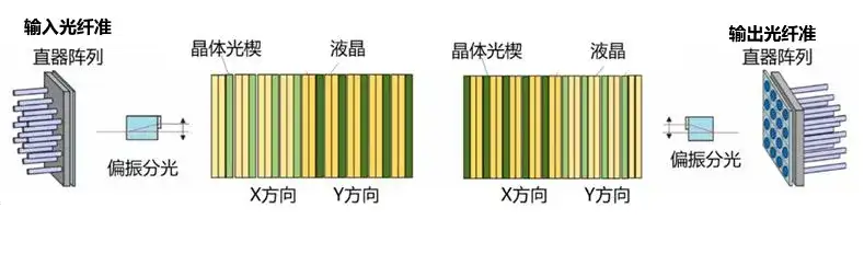
The switching principle of digital liquid crystal optical switching is: the LC tunable retarder rotates the polarization state of the incident light based on the electro-optic response property. Incident light with different polarization states produces different exit angles after passing through the birefringent crystal optical wedge, thereby realizing beam deflection, where the deflection angle is a fixed discrete value.
Among them, one stage of LC tunable retarder combined with a crystal optical wedge can achieve deflection at 2 discrete angles (2-state modulation). To extend the system switching dimension to M-port switching, a total of L stages of combinations are needed, satisfying 2^L>M. For example, for 256 ports, 8 stages of tunable LC and crystal optical wedge combinations are needed, which can be 4 stages in the x direction + 4 stages in the y direction to complete two-dimensional 256-port switching. This technology has very high assembly and adjustment requirements, and is expected to support up to 512 ports.
3. Direct Light Beam Steering DLBS Optical Switching
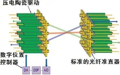
Direct light beam steering optical switching directly fixes the fiber collimators on piezoelectric ceramic actuators. The tail of each collimator is connected to piezoelectric ceramics, arranged into a two-dimensional collimator array. Two two-dimensional collimator arrays are placed face to face to form an optical switch matrix. Using the electromechanical coupling effect of piezoelectric ceramics, the collimator is driven to displace and tilt, so that the corresponding ports of the two arrays are matched and aligned, completing the channel connection and realizing the optical switching function.
In this scheme, the optical signal is input from the input collimator array port and directly transmitted to the output collimator for coupling output. In the process it does not need to be reflected or transmitted by any other optical system, so the optical signal transmission path is short, which helps reduce the optical signal transmission and coupling loss. However, as the number of channels increases and the cross-connect matrix scale grows, when large-angle cross-alignment such as diagonal ports is required, the rotation angle and displacement of the fiber collimator need to increase, which raises the performance requirements for the piezoelectric ceramic drive, and the space required to achieve the displacement increases, correspondingly increasing the optical signal transmission distance and further increasing the insertion loss, which to some extent restricts the scale of optical cross-connection. The core of direct light beam steering technology is solid-state drive technology, which uses the electromechanical coupling effect of piezoelectric ceramics to convert electrical energy into mechanical energy to produce displacement, directly driving the movement of the collimator or lens to change the beam transmission direction and achieve direct coupling of the corresponding collimator components. The DLBS optical switching principle is shown below.
4. Comparison of Optical Switching Technologies
The following table summarizes the technical comparison of the three different technical schemes:
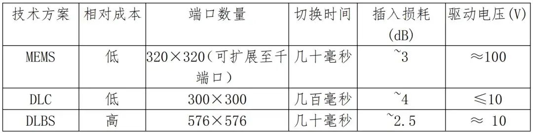
In summary, the optical switch realizes non-blocking switching from any input N port to output N port, which belongs to port switching. Its advantage is that it is independent of signal wavelength, modulation format, and rate, is protocol-transparent, and has extremely high scheduling efficiency.
Disclaimer: This account focuses on the exchange and sharing of technical content. All traceable content has been marked with its source. If a published article involves copyright or other issues, please contact us through a message in time for removal. Thank you for your understanding and support.
Download address:
If you have problems downloading, please contact WeChat “WaytoICT”
Related Reading
- Why Does Google Want to Develop OCS Optical Switches?
- What Is OCS? The Working Principle, MEMS Technology, and Industry Landscape of Optical Switches
- MEMS and OCS
Enjoy this article?
Subscribe to get new optical communication insights delivered to your inbox. Free, unsubscribe anytime.