Hollow-core fiber (HCF) is limited in its application to high-speed coherent communication and fiber optic gyroscopes due to its multimode characteristics, so there is an urgent need to efficiently filter out higher-order modes (HOM) within a short fiber length. However, existing designs find it difficult to simultaneously achieve ultra-low fundamental mode (FM) loss and ultra-high HOM suppression.
The paper below proposes a four-times-truncated double-nested nodeless anti-resonant hollow-core fiber (4T-DNANF), which significantly reduces FM loss and greatly increases HOM loss by precisely controlling the phase matching between the core mode and the cladding air modes.
The traditional 5-DNANF relies on the second cladding air gap (the green region in Figure 1a) to suppress HOM, but it must sacrifice the anti-resonant effect, resulting in a trade-off between fundamental mode loss and mode purity.
4T-DNANF innovatively applies a 120° truncation treatment to four large-diameter cladding glass tubes (Figure 1b), with two core purposes:
- Reduce the microstructure diameter (continuing the five-times truncation design idea);
- Block the phase matching channel: prevent the cavity mode behind the inter-tube gap from phase matching with the core fundamental mode, a matching that would cause the loss to surge by more than 10 times.
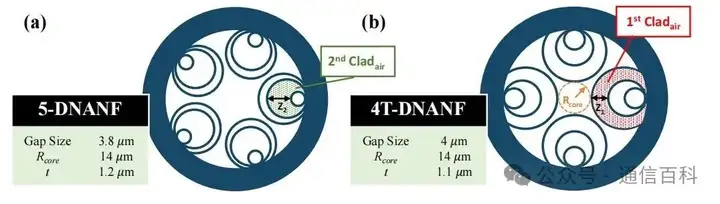
Figure 1: Cross-sections of (a) 5-DNANF and (b) 4T-DNANF.
Simulations show (Figure 2b) that when the first cladding air gap thickness ratio Z1/Rcore = 0.96, the LP11 mode couples with the first air gap mode adjacent to the core, achieving a HOM extinction ratio (HOMER) of 3.2×10⁵, while the fundamental mode confinement loss (CL) is below 0.01 dB/km. In contrast, under similar conditions (Figure 2a), 5-DNANF is forced to shrink the middle-layer glass tube size (Z2/Rcore = 0.22), and the fundamental mode loss rises to 0.5 dB/km.
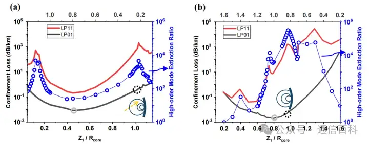
Figure 2: (a)(b) FEM simulations of LP01 (black) and LP11 (red) core modes
To improve fabrication feasibility, the study further explores a design that relaxes the inter-tube gap to 7 μm (Figure 3).
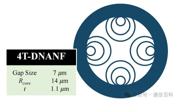
Figure 3: 4T-DNANF with a larger gap
The simulation is shown in Figure 4:
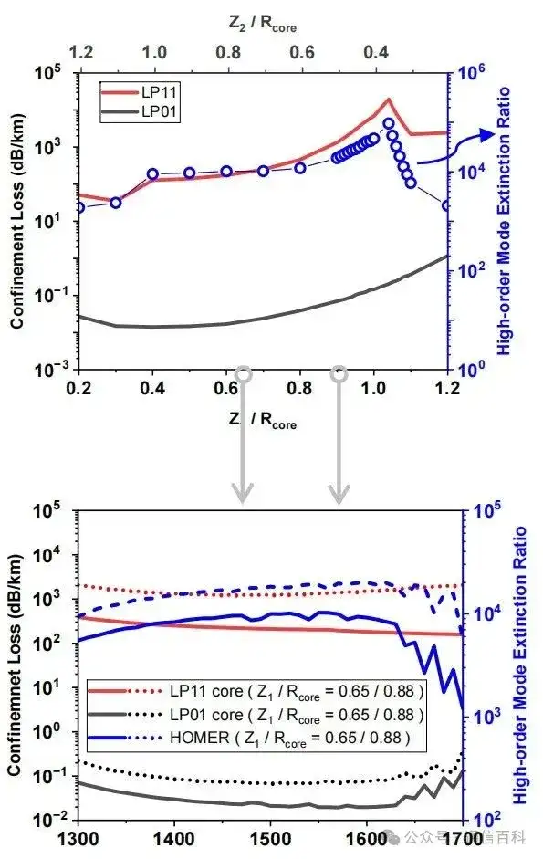
Figure 4 Simulation
It shows:
- When Z1/Rcore = 0.4-0.8: CL < 0.04 dB/km and HOMER ≈ 10⁴;
- When Z1/Rcore = 0.8-1.0: CL = 0.04 ~ 0.15 dB/km and HOMER > 10⁴.
This design expands the allowable gap from 5.4 μm (5-DNANF) to 7.6 μm (the black line in Figure 5 below), significantly reducing the risk of fiber drawing breakage and laying the foundation for subsequent experimental fabrication.
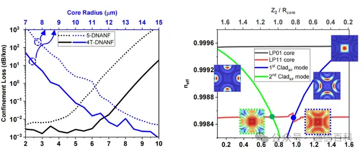
Figure 5: Confinement loss (CL) curve and effective refractive index distribution
The structure shown on the left above is the minimum achievable confinement loss (CL) curve: the black curve represents the relationship between CL and the inter-tube gap size under a fixed core radius and glass wall thickness; the blue curve represents the relationship between CL and the core radius under a fixed glass wall thickness with the gap size linearly scaled.
The right figure shows the effective refractive index distributions of the core LP01/LP11 modes (black/red), the first cladding air gap LP01 mode (blue), and the second cladding air gap LP01 mode (green), as well as their corresponding linear-coordinate mode field intensity distributions (|E|).
The five groups of experimentally fabricated fibers (Figure 6a-e) verify the flexibility of performance tuning:
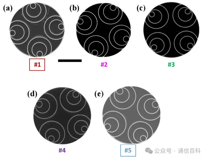
Figure 6a-e: (a)-(e) Scanning electron microscope (SEM) images of five groups of fabricated 4T-DNANF fibers
- Fiber #1 (Z1/Rcore = 0.65, 7 μm gap): fundamental mode loss 0.10±0.02 dB/km, LP11 mode loss 0.43 dB/m (HOMER ≈ 4,300)
- Fiber #2 (Z1/Rcore = 0.72): fundamental mode loss 0.15±0.02 dB/km, LP11 loss 1.2 dB/m (HOMER ≈ 8,000);
- Fiber #3 (Z1/Rcore = 0.79): fundamental mode loss 0.17±0.03 dB/km, LP11 mode loss 2.1 dB/m (HOMER ≈ 12,400);
- Fiber #4 (Z1/Rcore = 0.83): fundamental mode loss 0.19±0.03 dB/km, LP11 mode loss 3.8 dB/m (HOMER ≈ 20,000);
- Fiber #5 (Z1/Rcore = 0.88, 7 μm gap): fundamental mode loss 0.13±0.01 dB/km, LP11 mode loss 6.5 dB/m (HOMER = 50,000) — a record value.
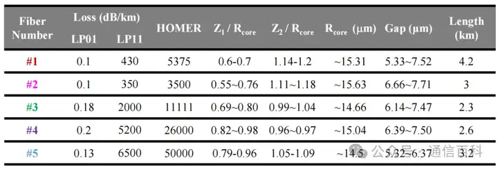
Table: Structural parameters of the five groups of fibers
The five groups of data reveal a strong positive correlation between Z1/Rcore and mode purity (Figure 7): as this parameter increases from 0.65 to 0.88, HOMER improves by more than 10 times, while the fundamental mode loss increases by only 0.03 dB/km (#1 vs #5), proving the effectiveness of the strengthened first cladding air gap coupling strategy.
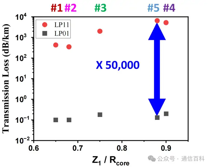
Figure 7: Average loss of LP01 and LP11 modes measured in the 1540-1560 nm range, and the corresponding HOMER
The synergistic advantages of 4T-DNANF:
- Small-core compatibility: at a core radius of 8 μm, CL is 1-2 orders of magnitude lower than 5-DNANF;
- Process robustness: a 7.6 μm gap tolerance (compared with 5.4 μm for 5-DNANF) reduces fabrication difficulty;
- Optical performance: C-band dispersion 2-4 ps/nm/km; no significant loss over 300 turns at an 8 cm bend radius.
The physical essence of this design lies in the dual role of the cladding air cavities, which are both part of the anti-resonant light-guiding structure and a selective HOM filter.
The four-times-truncated configuration, by precisely controlling the air gap size, breaks through the traditional multimode limitation and provides a new solution for long-distance communication and high-precision sensing. In the future, the focus will be on preform degassing (eliminating the CO₂ absorption peak), microbend loss suppression (optimizing coating stiffness), and surface scattering control, approaching the theoretical limit of 0.002 dB/km.
Thanks for reading!
Related Reading
- Yangtze Optical Fibre – Anti-Resonant Hollow-Core Fiber with Leaky-Mode Cavity
- Revealing: What Is Hollow-Core Fiber?
- Hollow-Core Fiber — What Is Photonic Bandgap Fiber?
Enjoy this article?
Subscribe to get new optical communication insights delivered to your inbox. Free, unsubscribe anytime.