Why Do Semiconductor Lasers Need a Narrow Linewidth?
At present, with the explosive growth in network traffic demand, the transmission rate of optical fiber communication has been greatly improved. One of the ways to increase the transmission rate is through higher and more complex modulation formats, which places higher requirements on the linewidth of lasers.
In addition, higher requirements on laser linewidth are imposed in fields such as spectroscopy, metrology, and biochemical sensing. For example, the linewidth of an FMCW lidar must be sufficiently small to ensure that light reflected back from beyond 200 m can still remain coherent with the reference light.
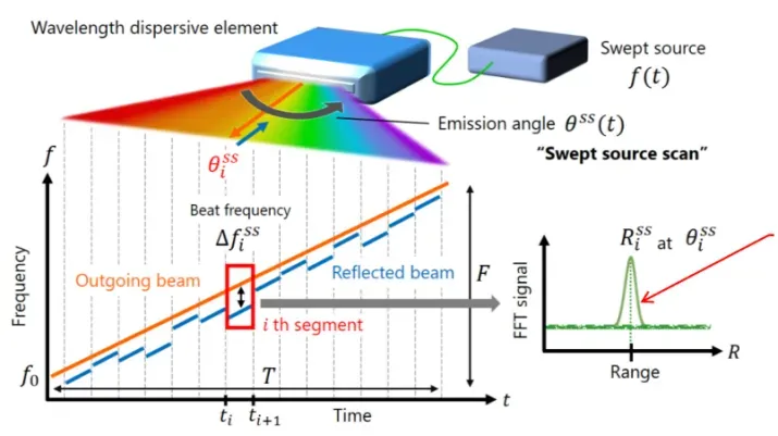
Figure: Schematic of FMCW lidar
Where Does the Linewidth of Semiconductor Lasers Come From?
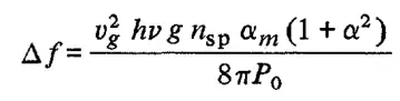
Most discussions of the linewidth theory of semiconductor lasers are based on the 1982 paper by C. H. Henry, “Theory of the Linewidth of Semiconductor Lasers.” This paper gives in detail the factors affecting the laser linewidth, and proposes the linewidth enhancement factor caused by the coupling effect between field amplitude and field phase. That is, phase and amplitude affect each other, thereby broadening the linewidth. The linewidth formula is as follows:
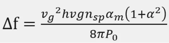
In the formula, Vg is the equivalent group velocity, hv is the energy of the laser line, g is the gain of the laser, nsp is the spontaneous emission factor, alpham is the facet loss, Po is the output power at the facet, and alpha is the linewidth enhancement factor.
According to the linewidth theory of semiconductor lasers described by Henry in 1982, the linewidth of a laser can be broadly attributed to the phase jitter of the optical field. Part of the phase jitter comes from the phase change caused by spontaneous emission, and another part comes from the phase change caused by the change in optical intensity and carrier density. The phase and amplitude of spontaneous emission light change instantaneously, and the amplitude in turn affects the magnitude of the phase.
Therefore, the change in phase can be considered to come from two aspects: one is the change in the phase of spontaneous emission itself; the other is the change in the phase of the optical field caused by the change in amplitude.
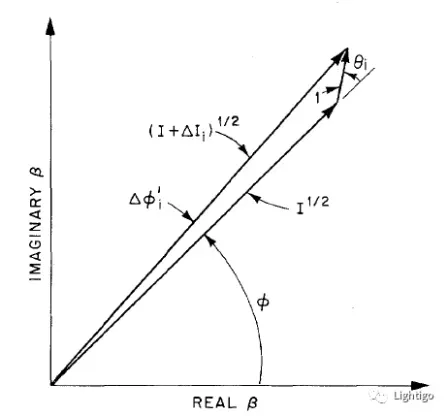
Figure: Change in the complex amplitude of the optical field caused by spontaneous emission
The figure above shows the change in the complex amplitude of the optical field caused by spontaneous emission. By constructing the triangle in the above figure, the phase change from spontaneous emission itself can be derived using trigonometric formulas (Formula 1), and the phase change of the optical field caused by the amplitude change can be derived using trigonometric formulas and rate equations (Formula 2).

(1)

(2)

(3)
The first term is the constant term, and the second term is the linewidth broadening. The Lorentzian linewidth expression is:
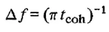
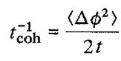
The coherence time tcoh can be expressed as
And the phase change can be obtained by integrating Formula (3):
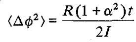
Taking the spontaneous emission rate R, then replacing it with group velocity, spontaneous emission factor, gain, etc., and replacing the optical intensity I with power P, the final formula is obtained:
Common Methods to Narrow the Linewidth of Lasers
Reducing loss and increasing power go hand in hand; according to the formula, they have a narrowing effect on the linewidth. Increasing the photon lifetime can increase the coherence time and also narrow the linewidth.
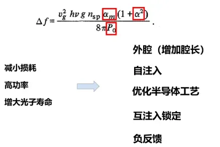
Figure: Five ways to narrow the linewidth
Below, the five methods of external cavity, increasing cavity length, self-injection, negative feedback, and mutual injection locking are introduced in detail.
- External cavity
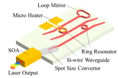
Figure: Using a silicon-based external cavity to narrow the linewidth. As shown in the figure above, using a silicon-based external cavity to narrow the linewidth has become quite common recently because hybrid integration processes are being used more and more widely. There are two benefits to using a silicon-based external cavity: first, the silicon-based external cavity has low loss; second, the external cavity is used to increase the cavity length; both of these characteristics can be used to narrow the linewidth.
- Increasing the cavity length
Increasing the cavity length is divided into increasing the physical cavity length and increasing the effective cavity length. Increasing the cavity length has the drawback that it cannot be increased indefinitely, because if the cavity length is too long, the longitudinal mode spacing becomes too close, raising the requirements on the filter.
The physical cavity length is to increase the length of the waveguide inside the cavity. As shown in Figure 5, the physical cavity length set by Eindhoven University of Technology is increased, filtering through two rings composed of MMI and waveguides, and expanding the tuning range through the Vernier effect, with an asymmetric MZI filter on top.
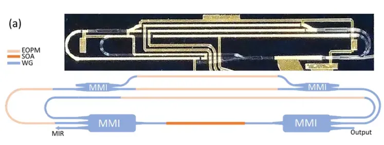
Figure: Example of increased physical cavity length
The effective cavity length is generally achieved through a high-Q ring. By controlling the coupling coefficient between the ring and the straight waveguide, the effective cavity length can be controlled. The figure above <using a silicon-based external cavity to narrow the linewidth> is an example of increasing the effective cavity length.
- Self-injection
Self-injection means that after the laser light is output from the laser, it is reflected by the external cavity and injected back into the resonant cavity for further stimulated emission. The carriers in the cavity change, causing the gain of other modes to decrease and the gain of the feedback mode to increase, with greatly increased intensity gain, suppressing other modes. The difference from the first external cavity method is that in the first method the external cavity is part of the resonant cavity, whereas here the external cavity is not.
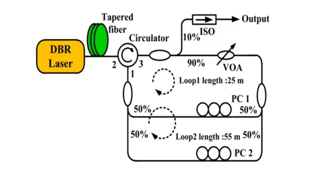
Figure: Resonance peaks generated by external cavity feedback
As shown in the figure above, since external cavity feedback will also generate some resonance peaks here, the Vernier effect produced by two rings is used to suppress these resonance peaks.
- Negative feedback
A high-Q cavity is not needed; only one filter is required. In this method, the operating point must be on the rising edge of the filter reflection spectrum, as shown in Figure (b) below. The formation of negative feedback is shown in the rightmost figure: if the frequency rises, the reflectivity rises, the photon concentration in the DFB cavity increases, the carrier concentration in the DFB cavity decreases, and due to the plasma effect the refractive index rises, so the output frequency decreases.
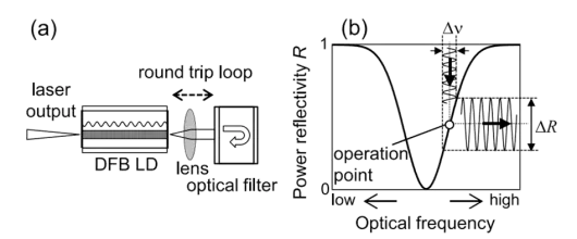
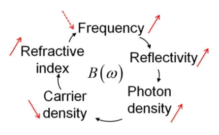
Figure: Formation process of negative feedback
- Mutual injection locking
In this method, as shown in the figure below, the entire system consists of two DFBs without isolators, one optical attenuator, two 1×2 power splitters, and two optical isolators. The fiber link delay between the two lasers is 10 ns. The coupling efficiency is adjusted through the optical attenuator, and the frequency noise is measured at ports 1 and 2. By fixing the current of one laser and adjusting the current and coupling strength of the other laser, the MIL mode is found.
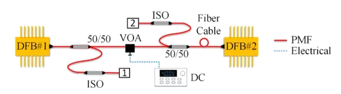
Figure: Mutual injection locking system
Basically, recent related papers all use one of the above methods to narrow the linewidth, with only minor differences. If there are any inaccuracies, please do not hesitate to point them out.
Related Reading
- Optical Modulation of Semiconductor Lasers!
- 2024 Semiconductor Industry Research Report – Automotive-Grade Chips
- 2024 Global and Taiwan Semiconductor Industry Outlook
Enjoy this article?
Subscribe to get new optical communication insights delivered to your inbox. Free, unsubscribe anytime.