The content is as follows, welcome to read:
- 1. Under what circumstances can NA accurately estimate the acceptance angle of an optical fiber?
- 2. Why is MFD an important parameter for single-mode fiber coupling?
- 3. Can NA accurately estimate the divergence angle of single-mode fiber output?
- 4. What factors affect single-mode fiber coupling efficiency?
- 5. Is the maximum acceptance angle of multi-mode fiber fixed?
Q1. Under what circumstances can NA accurately estimate the acceptance angle of an optical fiber?
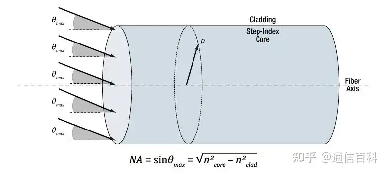
The maximum acceptance angle of multi-mode fiber can generally be estimated relatively accurately using the numerical aperture (NA), but this relationship does not apply to single-mode fiber.
The relationship between NA and the maximum acceptance angle (theta-max) can be obtained through geometric optics, and the formula is shown in the figure below.

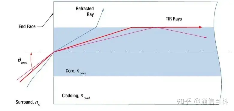
If the incident light is treated as individual rays, theta-max represents the ability of the fiber to collect off-axis light:
- Rays with an incident angle less than or equal to theta-max (red and pink) undergo total internal reflection (TIR) at the core-cladding interface and will be confined to propagate forward in the core;
- Rays with an incident angle greater than theta-max (blue) are eventually lost due to refraction.
Incident angle and fiber modes
Rays with an incident angle less than or equal to theta-max will be coupled into a guided mode of the multi-mode fiber. Generally speaking, the smaller the incident angle, the lower the order of the excited fiber mode. Most of the energy is concentrated in the low-order modes near the center, and the normally incident ray excites the lowest-order mode. Below are two propagation schematics of multi-mode fibers.

Graded-index multi-mode fiber

Step-index multi-mode fiber
Single-mode fiber is different
The NA calculated using the above formula is not the maximum incident angle of single-mode fiber, so it cannot characterize the light-receiving capability of single-mode fiber. In single-mode fiber, only the lowest-order guided mode excited by 0-degree incident light exists, and the propagation schematic is shown below.

Using NA to estimate the divergence angle of single-mode fiber output is very inaccurate. At this point, the beam diverges due to diffraction, and geometric optics does not consider this effect, so wave optics is needed. See Part 3 for how to use Gaussian beam propagation theory to calculate the single-mode fiber divergence angle.
Q2. Why is MFD an important parameter for single-mode fiber coupling?
When a beam propagates along a single-mode fiber, it maintains an intensity profile close to Gaussian, which can be characterized by the mode field diameter (MFD), that is, the width spanned when the intensity drops to 1/e2 of the peak.
Rule of thumb: MFD is about 1.15 times the core diameter.
The closer the incident light is to Gaussian light, the higher the coupling efficiency. If the incident light is Gaussian and the beam waist equals the fiber MFD, then very high coupling efficiency can be achieved. Substituting MFD for the beam waist diameter in the Gaussian beam formula can accurately calculate the coupling parameters and divergence angle of single-mode fiber.
Determining coupling parameters
Single-mode fiber has only one guided mode, which can be described by the Bessel function. Due to the similarity in shape, using a Gaussian function can simplify the fiber mode while providing accurate results.
The figure below shows the mode intensity profile of single-mode fiber; the incident light can be coupled into the guided mode only if it matches it.
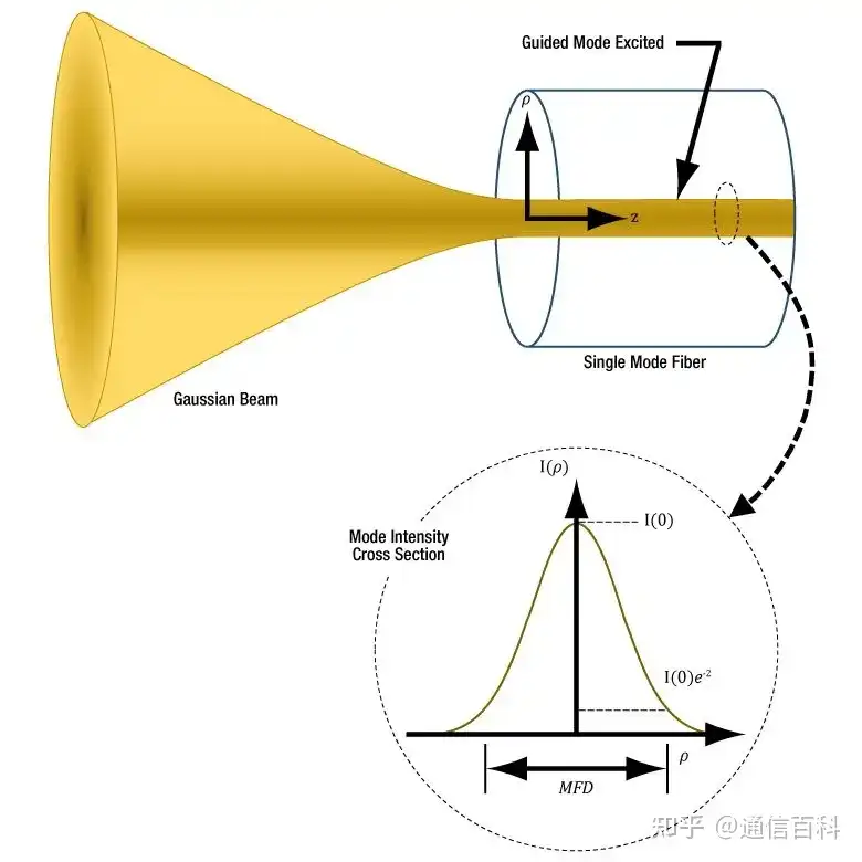
Single-mode fiber coupling
Improving single-mode fiber coupling efficiency requires that the beam waist of the incident Gaussian beam be located at the fiber end face, and that the beam waist intensity match and overlap with the mode intensity. If the beam waist diameter is not equal to the MFD, the beam intensity profile changes or deviates, or the beam does not enter along the fiber axis, these situations will all reduce coupling efficiency. See Part 4 for details.
Q3. Can NA accurately estimate the divergence angle of single-mode fiber output?
Using NA to estimate the divergence angle of single-mode fiber has a large error; a more accurate method is to use Gaussian beam propagation theory. The approximate formula for the far-field divergence angle of single-mode fiber is as follows, and the result is the divergence angle or acceptance angle in radians.
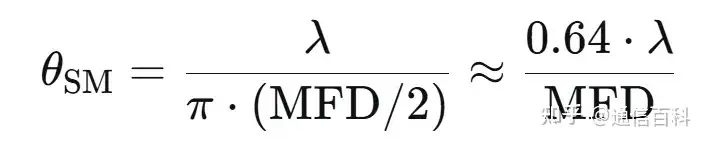
The output of single-mode fiber is similar to Gaussian light, and using geometric optics to calculate the divergence angle has a large deviation. The divergence angle calculated by geometric optics equals arcsin(NA), which only applies to general multi-mode fiber.
Single-mode fiber outputs a Gaussian beam, and the Rayleigh distance and the beam radius at point z are calculated using the following two formulas respectively.
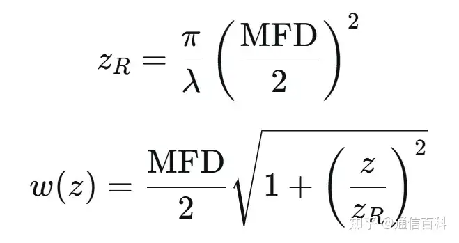
Based on this, the divergence angle of the single-mode fiber output beam can be accurately simulated, as shown in the figure below.
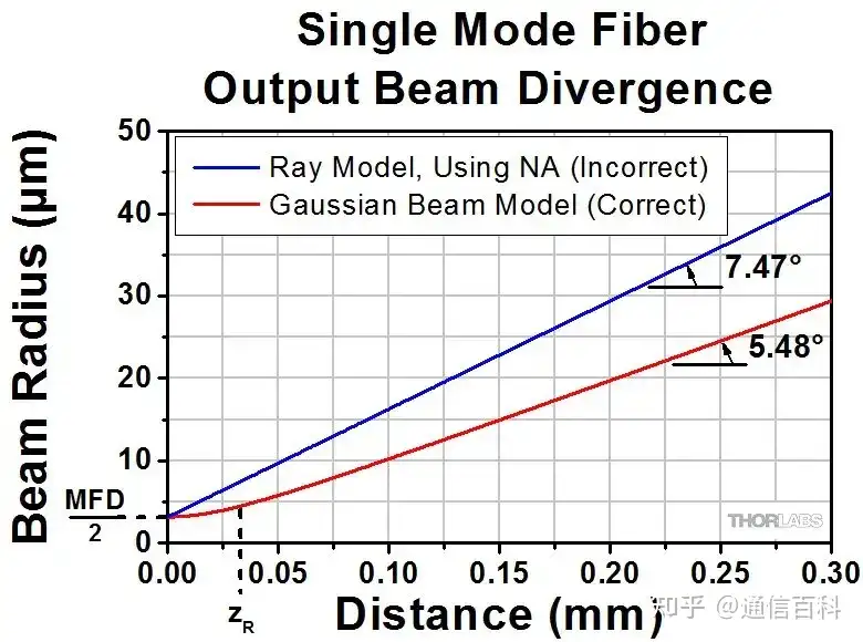
Obviously, using NA to calculate the divergence angle based on geometric optics theory has a large error. In this example, NA and MFD are equal to 0.13 and 6.4 um respectively. The operating wavelength is 980 nm, and the Rayleigh distance is 32.8 um.
It can be seen from the figure that within the Rayleigh distance, the beam divergence rate is not linear, while in the far field it can be regarded as approximately linear. The two angle values marked in the figure are calculated from the slopes of their respective curves. If the far-field approximation formula above is used, the result converted to an angle is 5.61 degrees, with a small error.
Q4. What factors affect single-mode fiber coupling efficiency?
Adjusting the angle, position, and intensity profile of the incident beam can improve the coupling efficiency of single-mode fiber. Assuming the fiber end face is planar and perpendicular to the axis, a beam satisfying the following conditions can achieve the highest coupling efficiency:
- Gaussian intensity profile
- Normal incidence at the fiber end face
- Beam waist located at the fiber end face
- Beam waist center aligned with the core center
- Beam waist diameter equal to the fiber MFD
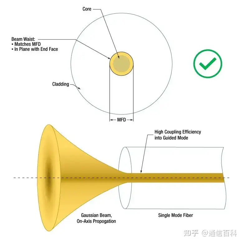
Correct coupling method
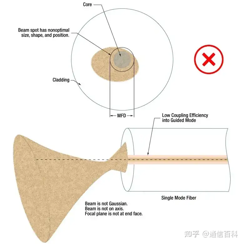
Incorrect coupling method
The light source may limit coupling efficiency
If the laser only emits the lowest-order transverse mode, the output approximates a Gaussian beam and can be efficiently coupled into single-mode fiber. However, the coupling efficiency of multi-mode lasers or broadband light sources with single-mode fiber is very low; even if focused into the core region, most of the light is leaked. This is because only part of the light from a multi-mode source matches the guided mode characteristics of single-mode fiber, so multi-mode sources can provide higher coupling efficiency with multi-mode fiber.
Regarding the coupling of optical engines, recommended reading:
1.6T DR8 Optical Engine and Coupling Methods
Q5. Is the maximum acceptance angle of multi-mode fiber fixed?
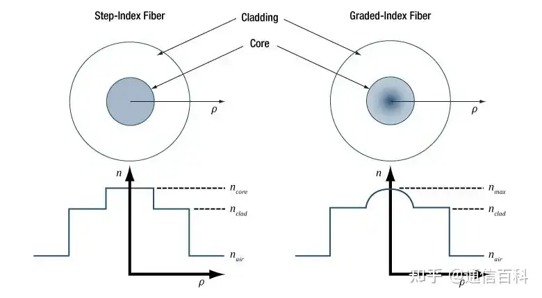
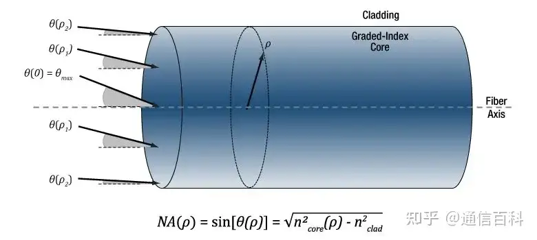
This question depends on the fiber type. For step-index multi-mode fiber, the maximum acceptance angle is the same at every point on the core. However, graded-index multi-mode fiber can only provide the maximum incident angle at the core center. The farther from the center, the smaller the maximum acceptance angle, approaching 0 near the cladding interface.
The figure below compares the difference between the two types of multi-mode fiber: on the left is step-index multi-mode fiber, where the refractive index is constant across the entire core. On the right is graded-index multi-mode fiber, where the refractive index varies with the core position, with the maximum refractive index generally at the center.
For step-index multi-mode fiber, if the incident ray angle is less than or equal to |theta-max|, it can be efficiently coupled into the step-index multi-mode fiber. The maximum acceptance angle is the same at every point in the core radius, as shown in the figure below.

For graded-index multi-mode fiber, since the core refractive index varies with radial distance, the acceptance angle also varies with radial distance. The acceptance angle at the core center is the largest, while the acceptance angle near the cladding boundary approaches zero, as shown in the figure below.
Step-index or graded-index?
Step-index multi-mode fiber can receive more light. All guided modes in graded-index multi-mode fiber have similar propagation speeds, which can reduce modal dispersion during beam propagation.
If the application requires coupling as much light as possible into the multi-mode fiber and is less affected by modal dispersion, step-index multi-mode fiber may be the better choice. Otherwise, graded-index multi-mode fiber should be considered.
Regarding vertical coupling and edge coupling, recommended reading:
Vertical Coupling & Edge Coupling: MEMS-Based Cantilever Edge Couplers
Enjoy this article?
Subscribe to get new optical communication insights delivered to your inbox. Free, unsubscribe anytime.