“Optical cable below, no excavation allowed.” What exactly is an optical fiber cable used for? And what are the consequences if it gets dug up?
When you stay at home, happily surfing the internet, watching HD IPTV, or browsing your social feed, if a nearby optical cable gets cut, all of these things may have to say goodbye.
That is because the optical fiber cable is an important part of communication transmission, bearing the great mission of transmitting network signals.
What Is an Optical Fiber Cable?
When talking about optical cables, we have to mention optical fibers. The yellow cable in the figure below is an optical fiber, commonly known as a pigtail. (For more details about optical fibers, see related content.)
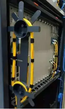
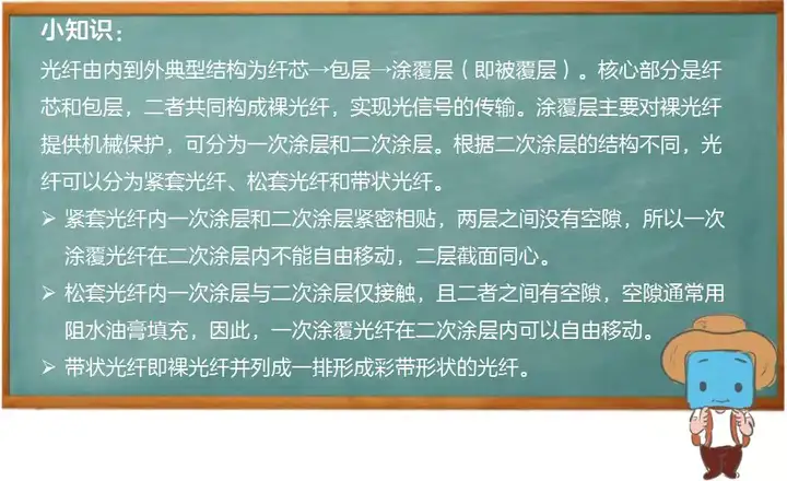
The optical fiber drawn from the operator’s equipment room needs to be connected to the optical modem in another room, a building, or even a home several kilometers away. You cannot just directly pull a single long optical fiber over. A single fiber is easily bent, damaged, and has poor impact resistance – just as a single chopstick is easy to break while a bundle of chopsticks is hard to break. To ensure the safety of the fiber, multiple fibers transmitting optical signals over long distances need to be bundled together and merged into an optical cable for laying. Moreover, to protect against high temperatures, rain, rodents, birds, and insects from the outside, multiple layers of armor need to be added: strength members, sheaths, and filling compounds.
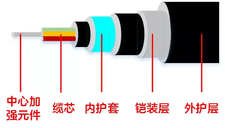
Now, let us look at the components of an optical fiber cable together:
- Cable core: composed of one or more optical fibers.
- Strength member: a component used to enhance the tensile strength of the cable. The material is generally steel wire or non-metallic fiber. It is usually located at the center of the cable core, and sometimes also arranged in the sheath.
- Sheath (the sheath is usually a three-layer structure of inner sheath -> armored layer -> outer sheath): used for waterproofing, moisture resistance, tensile, compressive, and bending resistance. The materials are polyethylene or polyvinyl chloride (PE or PVC), polyurethane polyamide, and metals such as aluminum and steel. The position is one or more cylindrical sheaths from inside to outside. The armored layer is generally steel wire or steel tape, located inside the outer sheath, mainly to prevent external force from damaging the cable.
In addition, there is filling material between the cable core and the sheath for moisture and water resistance. The filling material is generally a moisture-blocking gel.
What Are the Common Types of Optical Fiber Cables?
Just like snowflakes – although the basic shapes are similar, no two snowflakes in the world have exactly the same shape, and scientists have discovered tens of thousands of snowflake shapes – optical cables of different structures, when viewed from the cross-section, also look like beautiful snowflakes, each with a unique aesthetic. Classified by different structural shapes, optical cables are divided into stranded, slotted-core, loose-tube, and ribbon types.
- Stranded type: an optical cable formed by stranding loose-tube or tight-buffered fibers around a central strength member. Loose-tube or tight-buffered fibers refer to fibers with a protective jacket, whose materials mainly include polypropylene, nylon-12, polyester elastomer, fluoropolymer-46, fiber-reinforced plastic, and oriented stretch polymer. The stranded structure is similar to a traditional cable structure, so it is also called a classical optical cable. This type of cable can generally accommodate 6-12 fibers, and some accommodate 24 fibers. As the demand for fiber count increases, unit stranding has emerged, meaning the tube contains not just one fiber core but multiple fiber cores, expanding the fiber count that stranded cables can accommodate.
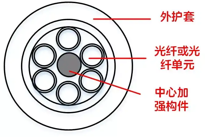
Stranded optical cables are easy to manufacture, the excess fiber length in the cable is easy to control, and the mechanical and environmental performance is good. They can be used for direct burial, duct, and aerial installation.
- Slotted-core type: since it is called slotted-core, there is undoubtedly a part called the slotted core inside the cable. This type of cable uses the slots of a plastic slotted core to accommodate the fibers. The cross-section of the slotted core may be V-shaped, U-shaped, or other shapes, and the longitudinal direction is helical or sinusoidal. One slotted core can hold 5-10 coated fibers.
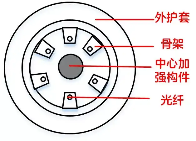
Slotted-core optical cables provide good protection for the fibers, good lateral pressure resistance, compact structure, and small diameter, and are suitable for duct installation. In addition, the fiber density is high, reaching thousands of fibers. However, slotted-core cables are complex to manufacture.
- Loose-tube type: similar to the slotted-core cable, there is a large tube in the center of the loose-tube cable to accommodate the fibers. This tube is called the large tube. The large tube contains coated fibers, which are placed without stranding inside the large tube. The strength member layer is wrapped around the large tube.
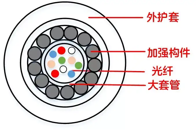
This type of cable has a simple structure and a simple manufacturing process; it protects the fibers better than other cable structures, resists lateral pressure, improves network transmission stability, and has a small cross-sectional area and light weight, making it especially suitable for aerial installation. The number of fibers in the tube is flexible, but the fiber count in the cable should not be too large.
- Ribbon type: ribbon optical cables are named after the ribbon fiber units accommodated in the cable. A ribbon fiber unit is a rectangular fiber combination formed by stacking several layers of ribbon fibers. Placing the ribbon fiber unit into a large tube gives a loose-tube ribbon cable; placing it into a slotted core gives a slotted-core ribbon cable; placing it into a fiber tube and stranding it around the central strength member gives a stranded ribbon cable. A schematic of a loose-tube ribbon cable is shown below:
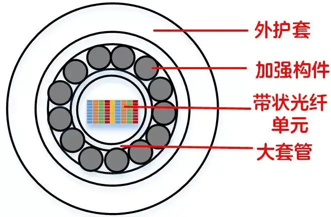
Ribbon optical cables have a small volume, which can increase the fiber density in the cable and accommodate more fiber cores, for example 320-3456 fibers. Ribbon cables are suitable for the currently rapidly developing fiber access networks.
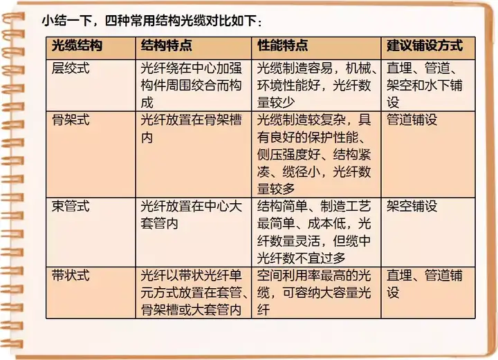
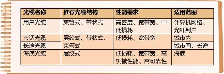
The user optical cables, local telephone optical cables, long-distance optical cables, and submarine optical cables that we often talk about are actually terms classified according to different uses of the cables. The correspondence between these cables and the cable structure is as follows:
What Does the Optical Cable Model Number Mean?
The exterior of an optical cable is printed with symbols of English letters plus numbers indicating the cable type. What do they mean?

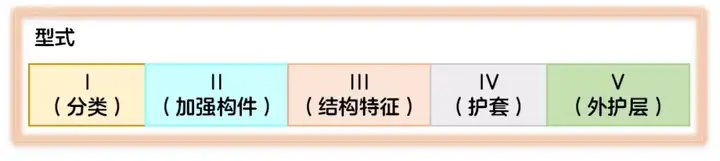
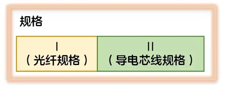
In China, the model naming of optical cables is standardized by the communications industry standard YD/T 908-2011 “Naming Method for Optical Cable Models”. The optical cable model consists of three major parts: the type, the specification, and the special performance mark, of which the special performance mark may be omitted.

Note: The type, specification, and special performance marks are separated by spaces.
The composition of the cable type is as follows:
The composition of the cable specification is as follows:
The meaning of Type I (classification) in the optical cable model is shown in the table below:
| Code | Meaning |
|---|---|
| GY | Outdoor (field) optical cable for communication |
| GYW | Micro outdoor optical cable for communication |
| GYC | Micro outdoor optical cable for communication laid by air blowing |
| GYL | Outdoor optical cable laid in micro-grooves on road surface for communication |
| GYP | Outdoor rat-proof drainage duct optical cable for communication |
| GJ | Indoor (central office) optical cable for communication |
| GJC | Micro indoor optical cable for communication laid by air blowing |
| GJX | Indoor drop optical cable for communication |
| GJY | Indoor/outdoor optical cable for communication |
| GJYX | Indoor/outdoor drop optical cable for communication |
| GH | Submarine optical cable for communication |
| GM | Mobile optical cable for communication |
| GS | Submarine optical cable for communication |
| GT | Special optical cable for communication |
The meaning of Type II (strength member) in the optical cable model is shown in the table below:
| Code | Meaning |
|---|---|
| (no symbol) | Metallic strength member |
| F | Non-metallic strength member |
The meaning of Type III (structural characteristics) in the optical cable model is shown in the table below:
| Structural Feature | Code | Meaning |
|---|---|---|
| Cable core fiber structure | (no symbol) | Discrete fiber structure |
| D | Fiber ribbon structure | |
| Secondary coating structure | (no symbol) | Loose-tube coated or uncoated fiber structure |
| S | Fiber bundle structure | |
| J | Tight-buffered fiber structure | |
| Loose tube material | (no symbol) | Plastic loose tube or no loose tube |
| M | Metallic loose tube | |
| Cable core structure | (no symbol) | Stranded structure |
| G | Slotted-core structure | |
| X | Central tube structure | |
| Water-blocking structure | (no symbol) | Fully dry or semi-dry |
| T | Filled structure | |
| Load-bearing structure | (no symbol) | Non-self-supporting structure |
| C | Self-supporting structure | |
| Suspension wire material | (no symbol) | Metallic strength suspension wire or no suspension wire |
| F | Non-metallic strength suspension wire | |
| Cross-section shape | (no symbol) | Circular |
| E | Elliptical | |
| B | Elliptical | |
| 8 | Figure-8 shape |
The meaning of Type IV (sheath) in the optical cable model is shown in the table below:
| Code | Meaning |
|---|---|
| Y | Polyethylene sheath |
| V | Polyvinyl chloride sheath |
| U | Polyurethane sheath |
| H | Low-smoke zero-halogen sheath |
| A | Aluminum-polyethylene bonded sheath (A sheath for short) |
| S | Steel-polyethylene bonded sheath (S sheath for short) |
| F | Non-metallic fiber-reinforced polyethylene bonded sheath (F sheath for short) |
| W | Steel-polyethylene bonded sheath with embedded steel wire (W sheath for short) |
| L | Aluminum sheath |
| G | Steel sheath |
When the optical cable has an outer sheath (i.e., Type V), the outer sheath may include part or all of the bedding layer, armored layer, and outer serving layer, so V is represented by two groups of numbers. Each group of numbers may consist of one or two digits. The meaning of Type V (protective layer) is shown in the table below:
| First Group (Armored Layer) | Second Group (Outer Serving Layer) | ||
|---|---|---|---|
| Code | Meaning | Code | Meaning |
| 0 | No armored layer | (no symbol) | No outer serving layer |
| 1 | Steel tube | 1 | Fiber serving |
| 2 | Wrapped double steel tape | 2 | Polyvinyl chloride sheath |
| 3 | Single fine round steel wire | 3 | Polyethylene sheath |
| 33 | Double fine round steel wire | 4 | Polyethylene sheath with nylon sheath |
| 4 | Single coarse round steel wire | 5 | Polyethylene protective sheath |
| 44 | Double coarse round steel wire | 6 | Flame-retardant polyethylene sheath |
| 5 | Corrugated steel tape | 7 | Nylon sheath with polyethylene sheath |
| 6 | Non-metallic wire | – | – |
| 7 | Non-metallic tape | – | – |
The specification of the optical cable model consists of the fiber specification, the communication wire specification, and the feeder wire specification, separated by “+”. The communication wire and feeder wire may be omitted in whole or in part.
- The fiber specification consists of the fiber count and the fiber category. The fiber category is shown in the fiber product classification table. The fiber count is represented by the actual effective number of fibers of the same category in the cable. The fiber category code should comply with the provisions of GB/T 12357 and GB/T 9771. The fiber categories are shown in the table below:
| Multimode Fiber | Single-mode Fiber | ||
|---|---|---|---|
| Code | Meaning | Code | Meaning |
| A1a.1 | Silica graded-index multimode fiber | B1.1 | Silica non-dispersion-shifted single-mode fiber, i.e., G.652.A / G.652.B fiber |
| A1a.2 | B1.2 | Silica cut-off wavelength shifted single-mode fiber, i.e., G.654 fiber | |
| A1a.3 | B1.3 | Silica extended wavelength band non-dispersion-shifted single-mode fiber, i.e., G.652.C fiber | |
| A1b | B2 | Silica dispersion-shifted single-mode fiber, i.e., G.653 fiber | |
| A1d | B4a | Silica non-zero dispersion-shifted single-mode fiber, i.e., G.655.A fiber | |
| A2a~A2c | Silica step-index multimode fiber | B4b | Silica non-zero dispersion-shifted single-mode fiber, i.e., G.655.B fiber |
| A3a~A3c | Silica graded-index, plastic-clad multimode fiber | B4c | Silica non-zero dispersion-shifted single-mode fiber, i.e., G.655.C fiber |
| A4a~A4d | Step-index plastic optical fiber | B4d | Silica non-zero dispersion-shifted single-mode fiber, i.e., G.655.D fiber |
| A4e | Graded-index or multi-step-index plastic optical fiber | B4e | Silica non-zero dispersion-shifted single-mode fiber, i.e., G.655.E fiber |
| A4f~A4h | Graded-index plastic optical fiber | B5 | Non-zero dispersion fiber for wide wavelength band optical transmission, i.e., G.656 fiber |
| – | – | B6a1 | Bend-loss-insensitive fiber for access networks, i.e., G.657.A1 fiber |
| – | – | B6a2 | Bend-loss-insensitive fiber for access networks, i.e., G.657.A2 fiber |
| – | – | B6b2 | Bend-loss-insensitive fiber for access networks, i.e., G.657.B2 fiber |
| – | – | B6b3 | Bend-loss-insensitive fiber for access networks, i.e., G.657.B3 fiber |
- The composition of the communication wire specification should comply with Table 3 of YD/T 322-1996. For example: 2x2x0.4 means 2 pairs of communication pairs with a nominal diameter of 0.4mm.
- The composition of the feeder wire specification should comply with Table 3 of YD/T 1173-2010. For example: 4×1.5 means 4 feeder wires with a nominal cross-sectional area of 1.5mm2.
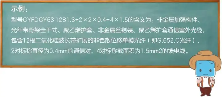
Now you should understand the meaning of “GYFTA53” mentioned earlier, right? Can you guess what it is?
[Answer: GY – outdoor optical cable for communication, F – non-metallic strength member, T – filled structure (here it represents the structural characteristics; since several items have no symbol, you cannot just look at the meaning of the letter T, and should supplement the structural meanings of the no-symbol items, so the complete structural meaning should be: loose-tube stranded filled structure), A – aluminum-polyethylene bonded sheath, 5 – corrugated steel tape armor, 3 – polyethylene sheath]
How Will Optical Fiber Cables Develop in the Future?
The structure of optical cables develops along with the development of optical networks and the requirements of the usage environment. The new generation of all-optical networks requires optical cables to provide wider bandwidth, accommodate more wavelengths, transmit at higher rates, be easier to install and maintain, and have a longer service life. The emergence of new cable materials has further promoted improvements in cable structure, such as the adoption of dry water-blocking materials, nanomaterials, and flame-retardant materials, which have significantly improved cable performance. In recent years, new types of cables have emerged, such as ecological optical cables, nanotechnology optical cables, and micro optical cables.
- Ecological optical cable: mainly considered from the perspective of environmental protection, solving the problem of environmentally unfriendly materials in cables. For example, PVC releases toxic gases when burned, and cable stabilizers contain lead. This type of cable is mainly used indoors, in buildings, and in homes. Some companies have already produced new materials for such cables, such as halogen-free flame-retardant plastics.
- Nanotechnology optical cable: cables using nanomaterials (such as nano optical fiber coatings, nano optical fiber gel, nano polyethylene sheath, nano PBT fiber sheath), taking advantage of the many excellent properties of nanomaterials, for example improving the cable’s resistance to mechanical impact.
- Micro optical cable: micro cables are mainly designed to cooperate with air-pressure or water-pressure installation construction systems. Various micro cable structures are already being designed and used, requiring a certain coefficient between the cable and the duct, accurate cable weight, and a certain stiffness. Micro cables and automatic installation methods are designed to meet the needs of future access networks, especially for structured cabling systems in user premises networks and cabling in intelligent ducts of smart buildings.
In summary, with the development of higher optical network technologies, optical cables continue to improve in structure, new materials, and performance to meet the diverse needs of future communications, such as the massive data carrying and massive connectivity requirements of the 5G era.

Related Reading
- What Is the PEACE Submarine Cable?
- G.654E Optical Fiber Cable Technology and Application Exploration.pdf
- G.654E Optical Fiber Cable Technology and Application Exploration.pptx
Enjoy this article?
Subscribe to get new optical communication insights delivered to your inbox. Free, unsubscribe anytime.