The more fundamental a principle is, the harder it is to write about. Take the “differential signal & common-mode rejection” I wanted to discuss today, for example — for a moment I didn’t know where to start.
Because there are simply too many excellent articles on the topic.
There’s no way around it: this concept is too ubiquitous in our optical device field. Let’s go straight to real-world examples.
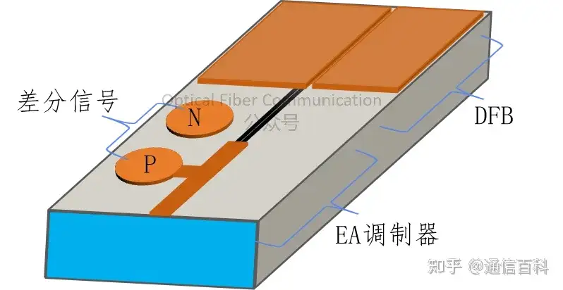
For instance, the “HGGenuine’s Differential Packaging Optical Transceiver Solution” we introduced before has, at its core, a packaging structure based on differential signal driving.
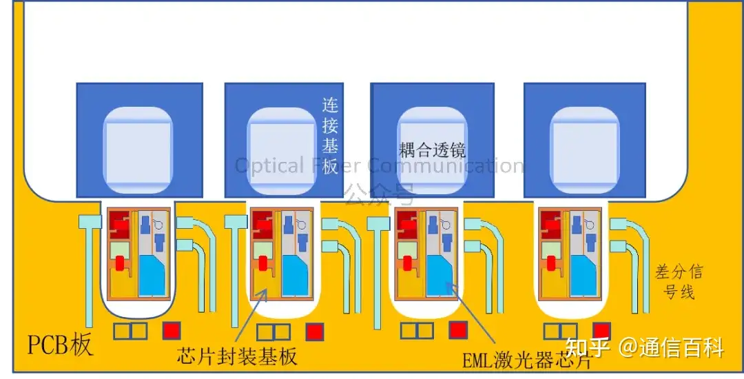
Another example: the 226G EML chip that Lumentum showcased at OFC 2025 also adopts a differential drive architecture.

So today, rather than laying out the textbook definitions of the basics, let’s stick close to the practical applications in optical devices. First, let’s look at two of the most basic schematic diagrams to build an intuitive impression:
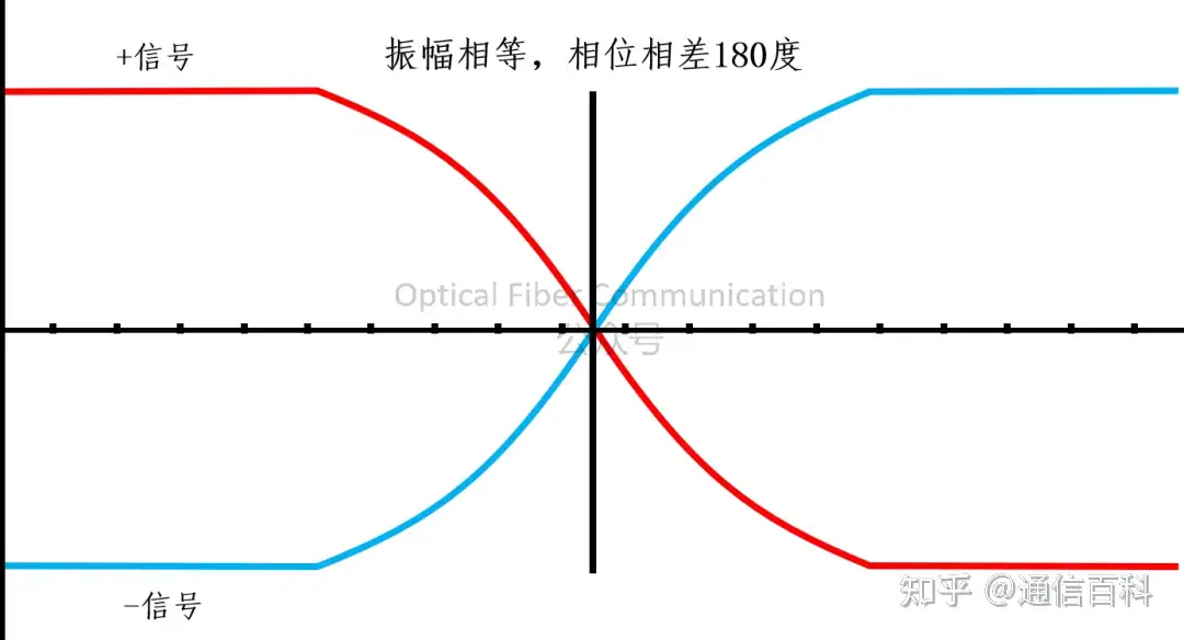
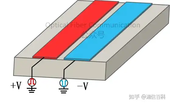
To help everyone understand better, let’s start from a very practical scenario — this is also my writing style.
At the receiver end of an optical transceiver, the optical signal is converted into a current by the photodetector, and this current is then sent into a TIA (transimpedance amplifier), where it is converted into a voltage signal.
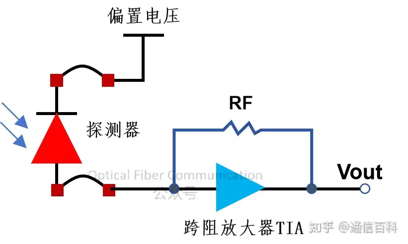
The current signal produced by the photodetector is very weak, and sending it directly to the downstream digital circuits (such as a limiting amplifier or clock recovery circuit) cannot be processed.
The core task of the TIA is to linearly and low-noise amplify this weak current signal into a clean, sufficient-amplitude voltage signal.
But if the traditional single-ended system is retained, a problem arises: during amplification, not only is the useful signal amplified, but the various noises coupled into the line from outside are also amplified together.
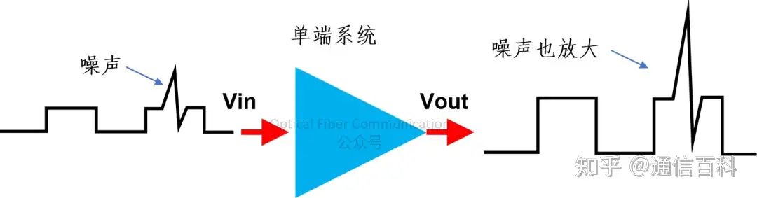
This is like answering a phone call in a noisy subway station — the surrounding ambient noise is so loud that it is hard to hear clearly what the other person is saying.
What if differential signaling is used instead? Differential signaling transmits a pair of signals with the same amplitude but exactly opposite phase through two wires.
During transmission, the signal can be decomposed into two components: the differential-mode signal (the useful information) and the common-mode noise (the useless interference).
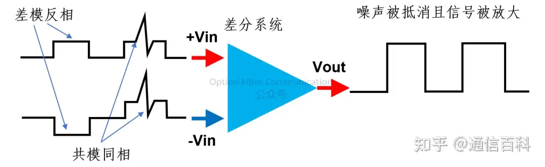
A differential TIA has strong rejection of the noise common to both wires (common-mode noise), and only responds to the voltage difference between the two wires (the differential-mode signal). That is, the common-mode noise generated in the line is suppressed.
That’s right — the common-mode noise rejection emphasized by the Lumentum EML chip mentioned earlier makes use of exactly this basic principle.
So, a core purpose of introducing differential signal driving in high-speed optical devices is to effectively suppress common-mode noise.
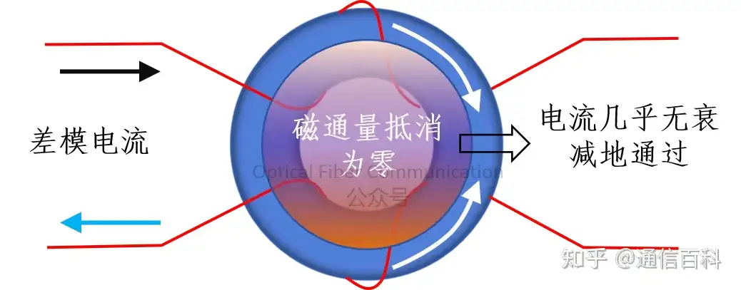
In addition, by exploiting the difference in magnetic field induction characteristics between differential-mode signals and common-mode noise, there is also a commonly used passive device called a common-mode filter, also known as a common-mode choke, which can be specially used to suppress common-mode noise transmitted on the line.
For common-mode noise, it presents a very high impedance:
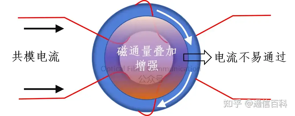
While for the signal, it is “transparent”:
Thanks for reading. If there are any inaccurate understandings, please forgive me and point them out!
Recommended reading:
ZTE: Innovation in Heat Sink and Coaxial Packaging Structures for Optical Transceivers
Huawei & HGGenuine: 50G PON Optical Transceiver Packaging Technology
Enjoy this article?
Subscribe to get new optical communication insights delivered to your inbox. Free, unsubscribe anytime.