At present, 100G line-side transmission solutions are very mature and widely commercialized. But with the arrival of the 5G era and the rapid rise of new services such as 4K, VR, cloud computing, and big data, optical networks are booming, and 100G optical networks will increasingly fail to meet bandwidth transmission requirements.
Beyond-100G, especially 400G solutions, will be an important evolution direction for ultra-high-speed, large-capacity optical transport networks, further improving network bandwidth and reducing per-bit transmission cost.
Let’s talk about 400G line-side transmission solutions together.
Classification of 400G Line-Side Solutions
We use the following simplified transmission structure diagram to represent the end-to-end WDM system:

As can be seen, the line-side transmission solution mainly includes three parts:
First is the transmitter modulation, such as whether you use PM-16QAM, PM-64QAM, or PM-QPSK;
Second is the line transmission, whether WSS flex grid, low-loss optical cable, and EDFA or Raman amplifiers are used;
Third is the receiver coherent detection, using which generation of SD-FEC, DSP, or optoelectronic integration.
At present, the 400G solutions of various vendors mainly include the following three types.
(1) 2x200G transmission solution (one 400G channel contains two 200G subcarriers)
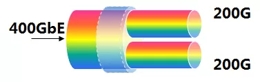
The 2x200G transmission solution is based on 200G PM-16QAM dual-carrier modulation. This solution balances transmission capacity and distance, reaching 25 Tbit/s in the C band, and is the more widely commercialized 400G solution.
(2) 4x100G transmission solution (one 400G channel contains four 100G subcarriers)
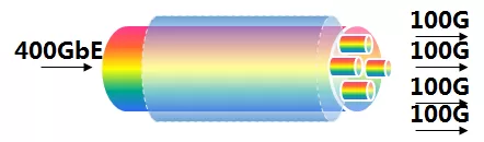
The 4x100G transmission solution is based on 100G PM-QPSK multi-carrier modulation. This solution prioritizes distance; without electrical regeneration, its transmission distance is far greater than the dual-subcarrier scheme of solution one. This solution reaches 15 Tbit/s in the C band, with the smallest transmission capacity.
(3) 1x400G transmission solution (one 400G channel with a single subcarrier)
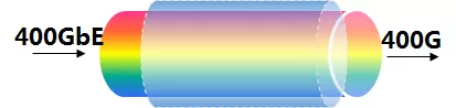
The 1x400G transmission solution is based on 400G PM-64QAM modulation, with a transmission distance smaller than the above two solutions, but reaching 25 Tbit/s in the C band.
How Is It Implemented Specifically?
Focusing on the currently mainstream commercial PM-16QAM dual-carrier modulation solution, let’s see how 400G transmission is implemented.
Step 1: Use a beam splitter to split each subcarrier (200G) into the X and Y perpendicular polarization directions.
(At this point, the 224 Gbit/s of the 200G signal is split into two, slowing to 112 Gbit/s.)

Note: The role of PM is to use a polarization beam splitter to separate the laser into optical signals in the x and y perpendicular directions, reducing the signal rate. At the same time, optical signals in other vibration directions are filtered out, reducing signal noise.
Step 2: Apply 16QAM modulation to the light in the X and Y perpendicular polarization directions.
(The 100G signal rate of 112 Gbit/s is processed serially and in parallel into two 56 Gbit/s signals, 112 Gbps / 2 = 56 Gbps, and then through phase-amplitude transformation, finally becomes 28 Gbaud.)

Note: 16QAM modulation, simply put, maps optical signals and electrical signals one-to-one by slowing down the rate.
Formula of the optical signal:
s(t)=I*Cosωt-Q*Sinωt=√(I²+Q²)Cos(ωt+θ)
The main parameters I/Q are the bit streams such as 0101.
Formula of the electric field:
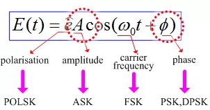
Through the constellation diagram, the I/Q of the optical signal can be mapped to the amplitude A and phase φ.

Because for the receiving end, recovering the phase-modulated signal is much more precise and easier than recovering the 0101 bit stream of I/Q. No matter how the signal is transmitted, even after long-distance transmission with interference and noise superimposed, the amplitude and phase information generally cannot be changed.
Step 3: Combine the modulated light in the X and Y perpendicular polarization directions back into one.

Step 4: The receiving end polarizes the incoming light from the line into two perpendicular directions, separating the X and Y polarization signals.

Step 5: Through coherent reception, identify information such as the phase of the light, and then convert the signal into an electrical signal.

Note: After the local oscillator source produces coherent conditions, the line light and the local oscillator light interfere, making it easier to recover the “phase-modulated” signal.
Step 6: Through ADC analog-to-digital processing, convert the electrical signal into a 01010 digital bit stream.

Step 7: DSP high-speed digital processing completes the entire 400G transmission; this step affects the final system performance.

In the DSP area, various vendors use different (patented) algorithms, and the quality of the algorithms is hard to describe in words or images. Therefore, experiments and tests are needed to know the final results achieved by each vendor.
In general, the purpose of introducing dual carriers, PM, and 16QAM in 400G line-side transmission technology is ultimately to reduce the rate (baud rate) of electrical-layer processing, to meet data processing under the current electronic bottleneck.

At the same time, introducing coherent detection, ADC, and DSP high-speed digital processing at the receiving end greatly improves the system’s chromatic dispersion tolerance and nonlinearity resistance at the electrical layer.

Related Reading
- Introduction to 400G Ethernet Transceivers
- 400G+ Optical Transmission Systems: Baud Rate, Modulation, and Spectral Technology
- What Is the 400G DWDM Optical Module Solution Like?
Enjoy this article?
Subscribe to get new optical communication insights delivered to your inbox. Free, unsubscribe anytime.