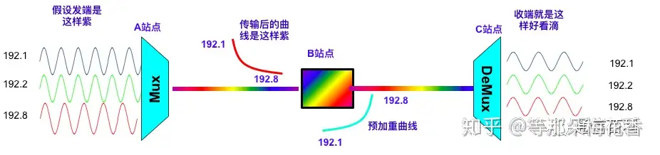
Before talking about pre-emphasis and equalization, let’s first look at what changes occur when a signal travels from node A through node B to node C. The ideal WDM signal transmission we hope for is as follows:
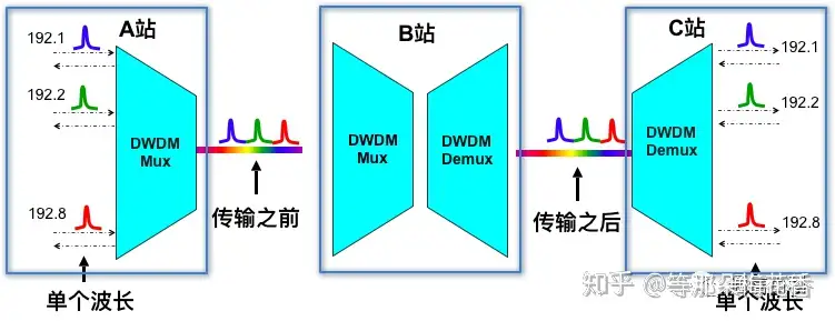
Before transmission, the waveform of each wavelength signal is in a certain form, and we hope the receiving end maintains the same formation. But in reality, it is like this:
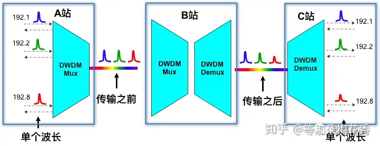
That is, after long-distance transmission and passing through multiple nodes’ multiplexing/demultiplexing or WSS devices, the higher-frequency 192.8 wavelength signal attenuates more than the lower-frequency 192.1 wavelength. This leads to severe degradation of the finally received signal. So why does this happen?
Here we introduce an important parameter of electromagnetic waves: S-parameters (Scattering parameters), the electromagnetic wave scattering coefficients. The input optical signal a1 passes through the optical devices in each node, reflecting part of the light b1, while the device’s own characteristics also absorb or lose part of the light, ultimately outputting b2 after attenuation.
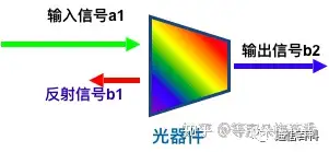
From this come the commonly mentioned insertion loss S21, and the less commonly mentioned return loss S11 (usually written in PDs). With the above and following figures, you can clearly understand S21 and S11.
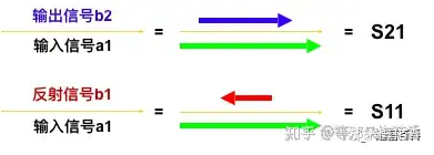
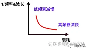
For systems with 40/80/96 waves, the S-parameters are actually a matrix sequence. Here we focus on S21 insertion loss. The above series of S21 forms an insertion loss curve:
This is what causes the problem mentioned at the beginning, with the received signal waveform as shown below:

To solve this problem (it should be clarified that amplifiers have different gains for different frequencies/wavelengths, and short and long wavelengths attenuate differently in the fiber, both of which cause this problem at the receiving end), pre-emphasis technology emerged.
High-frequency wavelengths attenuate quickly and low-frequency wavelengths attenuate slowly, so we boost the power of high-frequency signals (such as the 192.8 wave) or reduce the power of low-frequency wavelengths (such as the 192.1 wave) at the signal input. This is called pre-emphasis technology. In WDM systems, pre-emphasis is achieved by adjusting the optical power of individual wavelength signals, combined with OMU/WSS equipped with VOA adjustable optical attenuators and devices supporting power adjustment. Taking the 192.8 wave above as an example, we boost the power of the 192.8 wave signal.

Of course, pre-emphasis does not necessarily have to be at the input; it can also be at intermediate nodes. At intermediate nodes, the pre-emphasis of signals at various frequency/wavelengths has a certain inverse-proportional relationship, roughly as shown below:
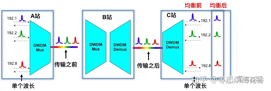
Above we discussed pre-emphasis; next let’s look at equalization. We already know that pre-emphasis is used at the transmitter, while equalization is generally at intermediate nodes and the receiving end, used to adjust the received optical wavelength signals. As mentioned above, after long distances and multiple nodes, high-frequency wavelengths attenuate quickly and low-frequency wavelengths attenuate slowly. Therefore, equalization increases the attenuation of low-frequency signals at the receiving end.

Enjoy this article?
Subscribe to get new optical communication insights delivered to your inbox. Free, unsubscribe anytime.