As the characteristics of multicore fiber (MCF) have been clarified, various MCFs have been proposed and demonstrated. Due to limited space, although many other characteristic MCFs have been proposed, below we only show a few limited MCF examples.
As shown in the SC-MCF section, very few MCFs have actually been demonstrated for communication so far, although some theoretical work proposed and studied SC-MCF in the early stages of SDM fiber research.

This may be because most fiber manufacturers focus on other types of SDM fibers, such as UC-MCF, RC-MCF, and non-MCF few-mode fibers, which are easier to manufacture and use. The lack of multiplexers/demultiplexers (MUX/DEMUX) for the low-XT (coupling) modes of the eigenmodes also poses challenges to fiber research. Although some MUX/DEMUX methods have been proposed, low-XT MUX/DEMUX has not actually been demonstrated. Once low-XT MUX/DEMUX of eigenmodes is demonstrated, research on SC-MCF fibers may accelerate.
In the RC-MCF section, many fibers with different core counts are shown, but these fibers can be divided into three types:
(1) MCF with a group of coupled multiple single-mode cores [1,2,4,5], (2) MCF with multiple uncoupled groups of coupled multiple single-mode cores [3], (3) MCF with a single group of coupled multiple few-mode cores [6].

Type (1) is the main type of RC-MCF, and various long-distance or real-time MIMO DSP transmission experiments have been conducted using these RC-MCFs. Among SDM fibers, the lowest loss at 1550 nm is 0.158 dB/km and the lowest SMD is 3.14 ps/√km, achieved by an RC-MCF with four Ge-free silica cores, with an effective core mode area expanded to 112 μm² at 1550 nm. This fiber has been demonstrated to outperform equivalent low-loss, large-effective-area SMF fibers in nonlinear tolerance and transmission performance. Up to 12 cores can be packed into a standard 125 μm cladding with suppressed SMD.
If the total number of spatial channels in type (2) RC-MCF increases, the computational complexity of MIMO DSP becomes a problem, but dividing the spatial channels into multiple uncoupled groups (as in type (2) RC-MCF) helps suppress MIMO complexity.
In type (3) RC-MCF, a coupled 3-mode (2-LP-mode) 7-core fiber was proposed to further increase the spatial density in a standard-diameter cladding. Although the intra-core coupling between LP01-based and LP11-based modes is considerably suppressed, the inter-core coupling within LP01-based or LP11-based modes is well suppressed within each (LP01-based or LP11-based) mode group.
For uncoupled UC-MCF fibers, homogeneous MCFs with identical cores are superior in terms of optical property uniformity among cores, while heterogeneous MCFs with different cores are superior in XT suppression. Due to compatibility with conventional SMF transceivers, MCFs with single-mode cores are more practical, while MCFs with few-mode cores are suitable for achieving extremely high capacity using a very large number of spatial channels. Some MCFs use quasi-single-mode (QSM) cores (i.e., few-mode cores) to improve optical confinement of the core and suppress XT.
From the different research directions, these uncoupled MCFs can be divided into two categories:
A: High spatial-channel-count MCFs for extremely high capacity; B: MCFs proposed for near-term practical implementation.
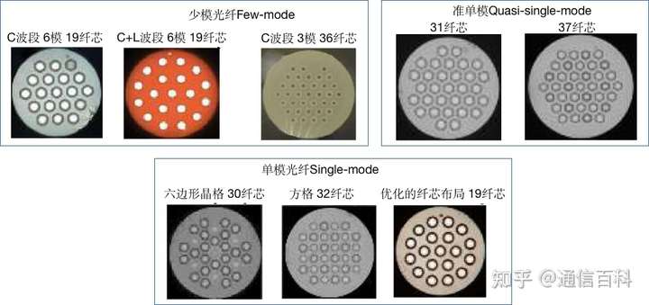
Type A MCFs are basically designed with more than 10 cores and a cladding diameter greater than 200 μm to achieve ultra-high transmission capacity per fiber. As shown below, for example, the highest fiber transmission capacity of 10.16 Pb/s was achieved on the C+L band (1530-1625 nm) using FM-MCF (6-mode 19-core fiber) (far left in the figure below), but it still faces many technical/economic challenges for practical implementation, such as DGD/MDL suppression in FM-MCF.
According to their implementation methods, type B MCFs can be further divided into three types.
Type 1 is an MCF with a standard 125 μm diameter cladding, as shown below.
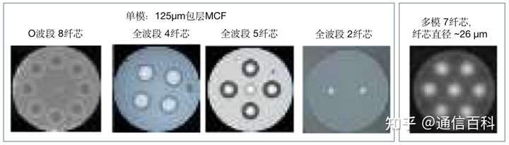
The standard 125 μm diameter cladding achieves field-verified mechanical reliability and can suppress increases in production cost, because longer fiber can be drawn from the preform compared with thicker fibers. The 125 μm cladding MCF is also compatible with conventional drawing and cabling techniques and connector ferrules. It is reported that optical properties including XT do not degrade due to cabling.
In an interoperability demonstration, using 125 μm cladding 4-core fibers made by three fiber manufacturers with common specifications and MCF connectors, plus multicore erbium-doped amplifiers made by three companies, transmission of 118.5 Tb/s was achieved over a distance of 316 km.
Type 2 is an MCF with core arrangements compatible with transceivers, enabling end-to-end MCF transmission links. For example, a 234-core layout MCF was code-designed with Si Photonics chips, so the core array can match the grating coupler array. VCSELs (Vertical-Cavity Surface-Emitting Lasers) and photodiode arrays were developed for 125 μm cladding multimode 7-core fiber, so the outer 6 cores can match the VCSEL and PD arrays.
Type 3 is an MCF with a non-circular cladding for easy rotational alignment. The non-circular cladding enables passive rotational alignment, but manufacturing deviations in core position and cladding size limit alignment accuracy. In addition, to avoid deformation of the cladding shape due to surface tension, the drawing speed is limited.
Related Reading
- What Types of SDM Space-Division Multiplexing Fiber Are There?
- Space-Division Multiplexing Fiber
- Sumitomo: A Multicore Fiber with Low Polarization Mode Dispersion
Enjoy this article?
Subscribe to get new optical communication insights delivered to your inbox. Free, unsubscribe anytime.