If you are interested in semiconductors / optical devices / optical transceivers / optical fiber communication
Please follow us!
Optical systems originally began with a simple digital modulation scheme, namely on-off keying, or OOK. In this scheme, the binary electronic bit stream modulates the intensity of the optical carrier within the optical transmitter. The resulting optical signal, after being transmitted through the fiber link, falls directly on the optical receiver, which converts it back into the original digital signal in the electrical domain.
This scheme is also called direct-detection intensity modulation (IM/DD).
In radio and microwave communication systems, many other schemes transmit information by modulating the amplitude and phase of the carrier. Although the use of such modulation formats in optical systems was considered as early as the 1980s, it was not until after 2000 that phase modulation of the optical carrier regained attention, mainly because phase modulation has the potential to improve the spectral efficiency of wavelength division multiplexing systems.
There are two motivations for this phase-encoded modulation. First, compared with direct detection, appropriate design can improve the sensitivity of the optical receiver. Second, phase-based modulation techniques can improve the spectral efficiency of wavelength division multiplexing systems, thereby making more effective use of fiber bandwidth.

Both the amplitude and phase of the optical carrier can be used to encode the information to be transmitted. In IM/DD systems, the binary amplitude shift keying (ASK) format is used, in which the peak amplitude (or intensity) of the carrier takes two values, one of which is close to zero (also called the OOK format). Below we look at the phase-based advanced modulation formats used in modern optical systems.
1. Optical Signal Encoding
The electric field E(t) associated with the optical carrier has the form

where e is the polarization unit vector, a is the amplitude, φ is the phase, and ω0 is the carrier frequency. Introducing the complex phasor as A = aeiφ, a constellation diagram can be constructed in which the real and imaginary parts of A are plotted along the x-axis and y-axis, respectively. For the OOK format, such a diagram has two points on the real axis, indicating that whenever a bit 1 is transmitted, only the amplitude a changes from 0 to a1 (the phase remains unchanged).

The simplest PSK format is one in which the phase of the optical carrier takes two different values (see the figure below), usually chosen as 0 and π. Coherent detection is a necessary condition for this format, because if the optical signal is directly detected without first being coherently mixed with a local oscillator, all information is lost. At a given bit rate B, using the PSK format requires the phase of the optical carrier to remain stable for a time much longer than the bit duration (Tb = 1/B). This requirement places strict conditions on the tolerable spectral linewidth of the laser and local oscillator, especially when the bit rate is relatively small.

The phase stability requirement can be greatly relaxed by using a variant of the PSK format, namely differential PSK, or DPSK. In the case of DPSK, information is encoded through the phase difference between two adjacent bits. If only two phase values are used (differential BPSK, or DBPSK), the phase difference Δφ = φk – φk-1 will vary between π or 0 depending on whether the k-th bit is a 1 bit or a 0 bit. The advantage of the DPSK format is that as long as the carrier phase remains relatively stable over the duration of two bits, the received signal can be successfully demodulated.
The BPSK format cannot improve spectral efficiency, because it uses only two different carrier phase values. If the carrier phase is allowed to take four different values, usually chosen as 0, π/2, π, and 3π/2, two bits can be transmitted simultaneously. This format is called quadrature PSK (QPSK), and its differential version is called DQPSK. The figure below (a) shows the QPSK format using a constellation diagram, which helps understand how two bits are transmitted simultaneously. As shown, the four possible combinations of two bits, namely 00, 01, 10, 11, can be assigned in a unique way to the four values of the carrier phase. Therefore, when using the QPSK (or DQPSK) format, the bit rate is effectively halved.

The effective bit rate is called the symbol rate, in units of baud. In this term well-known in the radio and microwave communication field, the phase value represents the transmitted “symbol,” and the number of symbols M represents the size of the alphabet. The symbol rate Bs is simply related to the bit rate B by B = log2(M)Bs.
Therefore, if the QPSK format with M = 4 is used at Bs = 40 Gbaud, the information transmission rate is 80 Gb/s, thereby doubling the spectral efficiency of the wavelength division multiplexing system. Of course, if the so-called 8-PSK format is used, with 8 different carrier phase values, the bit rate will be tripled. Figure (b) 8-BPSK above shows the case of allocating 3 bits per symbol.
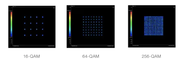
If the amplitude of the signal is also allowed to change from one symbol to the next, more complex modulation formats can be designed. As shown in figure (d) above, the amplitude can have two possible values, each amplitude having four possible phases. Another example is shown in figure (c) above, where 16 symbols are located on a square grid and can transmit 4 bits simultaneously. This modulation format is called 16-QAM, where QAM stands for quadrature amplitude modulation. Using the QAM modulation scheme allows data rates of 400 Gbps or higher. The modulation and demodulation of QAM signals are more complex, and the cost is higher than other formats.

Obviously, at a given bit rate, this method can further reduce the symbol rate by increasing the number of symbols M. It should be emphasized that the assignment of bit combinations to the various symbols in the figure above is not arbitrary. A coding scheme called “Gray coding” maps different bit combinations to different symbols such that only one bit changes between two adjacent symbols separated by the shortest distance in the constellation diagram. If Gray coding is not used, a single symbol error will produce errors in multiple bits, increasing the system bit error rate.
By exploiting the state of polarization (SOP) of the optical carrier, the spectral efficiency can be further doubled. In the case of polarization division multiplexing (PDM), each wavelength is used to transmit two orthogonally polarized bit streams at half the original bit rate. It may seem surprising that this scheme can work, because the SOP of the channel is not fixed within the fiber but changes randomly due to birefringence fluctuations.

However, it is not difficult to see that PDM can be successfully adopted as long as the two PDM channels of each wavelength remain nearly orthogonally polarized over the entire link length. This can only be achieved if the effects of PMD and nonlinear depolarization are relatively small over the entire link length. If coherent detection is used at the receiver, it is possible to separate the two PDM channels through an appropriate polarization diversity scheme. The combination of QPSK (or DQPSK) with PDM can reduce the symbol rate to one quarter of the actual bit rate, thereby improving the spectral efficiency by 4 times. This dual-polarization QPSK format is attractive because a 100-Gb/s signal can be transmitted over a fiber link designed for 10-Gb/s signals with a 50-GHz channel spacing, and it was already used in commercial systems by 2010.
There is still one design issue to solve. In the case of purely phase-encoded signals, such as the QPSK format shown in figure (a) above, when the NRZ format is used, the amplitude or power of the data stream is initially constant over time, because each symbol occupies the entire time slot assigned to it. This situation has two effects.
- First, the average power entering each channel is greatly increased, which is generally undesirable.
- Second, as the data stream passes through the fiber, various dispersion and nonlinear effects cause time-varying power changes, which affect system performance.
Another approach is to use a modulation format in which all symbol time slots contain an optical pulse whose phase changes with the transmitted data. Adding the prefix RZ before the format used for data transmission (such as RZ-DQPSK) indicates this situation.
2. Amplitude and Phase Modulators
The implementation of any PSK format requires an external modulator that can change the optical phase according to the applied voltage through a physical mechanism called electro-refraction. Any electro-optic crystal with the correct orientation can be used for phase modulation. In practice, LiNbO3 waveguides are usually used. The phase shift δφ occurring inside the waveguide has a simple relationship with the refractive index change δn: δφ = (2π/λ)(δn)lm, where λ is the wavelength of the input light and lm is the length of the modulator. The index change δn is proportional to the applied voltage. Therefore, by applying the required voltage, any phase shift can be applied to the optical carrier.
In most practical cases, an amplitude modulator is also needed. It can be used to convert the CW continuous signal of a DFB laser into an RZ pulse sequence. It can also be used to simultaneously modulate the amplitude and phase of the incident light. Common designs use a Mach-Zehnder (MZ) interferometer to convert the voltage-induced phase shift into amplitude modulation of the input signal.
The figure below shows a schematic design of a LiNbO3 MZ modulator.

The input field Ai is split into two equal parts at one Y-junction, and after applying different phase shifts by applying voltages to the two waveguides constituting the two arms of the MZ interferometer, they are recombined at another Y-junction. These phase shifts are usually represented by φj(t) = πVj(t)/Vπ, where Vj is the voltage applied to the j-th arm (j = 1, 2), and Vπ is the voltage required to produce a π phase shift. This parameter is known for any LiNbO3 modulator, usually between 3 and 5 V.

The transfer function of the modulator is easily obtained and has the form:

This shows that the MZ modulator affects both the amplitude and phase of the incident light. If we choose the voltages on the two arms such that V2(t) = -V1(t) + Vb (where Vb is a constant bias voltage), then it can act as a pure amplitude modulator, because φ1 + φ2 reduces to a constant. In this case, the power transfer function of the modulator has the form:

If the same voltage is applied to both arms, so that φ1 = φ2, this MZ modulator can act as a pure phase modulator, changing only the phase of the input signal by φ1(t).
Although a single MZ modulator can simultaneously change the amplitude and phase of the input light by appropriately choosing the arm voltages V1 and V2, it cannot independently modulate two quadratures. An IQ modulator can solve this problem. It consists of three nested MZ modulators, as shown in the figure below, where each arm of the outer MZ interferometer contains its own MZ modulator. By appropriately choosing the applied voltages, the entire complex plane in the constellation diagram can be covered.

Take the QPSK modulation format as an example. In this case, the two inner MZ modulators operate in the so-called push-pull mode, that is, φ2 = -φ1. In addition, the voltage changes such that the transfer function tm takes the values ±1, corresponding to the two phase shifts of 0 and π, depending on the transmitted data bit. The outer modulator is biased to produce a constant π/2 phase shift between the signals of its two arms. Therefore, the output has four possible phase shifts, namely:

The corresponding four phase values are π/4, 3π/4, 5π/4, and 7π/4, suitable for creating a QPSK-modulated data stream. When the two inner MZ modulators are driven by differentially encoded electrical signals, this modulator can also be used to create a DQPSK symbol stream.
End
………………………………………………
Related Reading
- How Much Bandwidth Gain Does Raising the Modulation Level Bring?
- 400G+ Optical Transmission System: Baud Rate, Modulation and Spectrum Technology
- 5G NR Modulation and Coding Scheme – Modulation and Code Rate
Enjoy this article?
Subscribe to get new optical communication insights delivered to your inbox. Free, unsubscribe anytime.