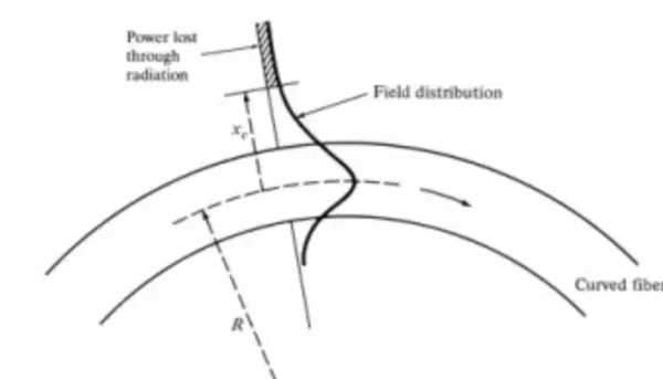
Among the optical losses of fiber in applications, a relatively complex type is microbend loss. With the development of components and fibers, microbend loss has become a loss factor worthy of attention. Components increasingly introduce direct optical switching to replace electrical switching, and in a very small space, fiber is prone to long-term stress. For optical fiber, thinner fiber – that is, fiber with a smaller diameter – whether by reducing the coating thickness or the cladding diameter, increases the risk of microbend loss. Multi-core fiber is similar, as its effective cladding thickness is also greatly reduced, all of which increase the risk of microbend loss.
Microbend loss and macrobend loss are a corresponding pair of losses, but from the perspective of the mechanism by which the loss occurs, there are relatively obvious differences between the two. In practical applications, it is very necessary to distinguish whether the loss comes from microbend or macrobend according to the nature of the loss, as this involves locating the problem and the approach to solving it.
From the perspective of geometric deformation: microbend loss is actually a loss introduced by tiny deformation of the fiber, whereas macrobend loss is a loss introduced by real bending, with the fiber’s outer diameter remaining ideally unchanged. This is clearly different geometrically. The tiny deformation of the fiber can be treated as a high-frequency perturbation of the fiber’s longitudinal geometric circumference. This perturbation has two attributes, amplitude and frequency, and the microbend scenario comes from high frequency and low amplitude. The external perturbation can be simulated as random changes in frequency and amplitude over time. Performing a Fourier transform on this random change, where the amplitude is equivalent to power, yields the corresponding relationship between power spectral density and spatial frequency.

This is also relatively easy to understand intuitively and to draw a qualitative conclusion: when the perturbation frequency is very high, the fiber deformation becomes uniform, and the impact of microbend loss is not large; while when the perturbation frequency is very low, real bending may form, and macrobend loss becomes dominant. The two also differ in loss mechanism. In macrobend loss, the fundamental mode of the fiber (single-mode fiber) can be considered to have its mode field distribution spread toward the bending side, and the part that spreads deep into the cladding forms radiation and gradually loses power. In microbend loss, when the fundamental mode propagating in an ideal fiber is perturbed, part of the power is coupled into various higher-order modes. The power carried by these higher-order modes is radiated out of the fiber as the propagation distance increases, and of course may also be coupled back into the fundamental mode.

The analysis of microbend loss typically uses mode coupling theory, and its basic relationship is somewhat complex.

Here C is the coupling coefficient between the fundamental mode and a certain higher-order mode, which reflects how much power is coupled from the guided mode to a higher-order mode or cladding mode (single-mode scenario). Qfiber is the perturbation of the fiber under direct stress, and Qenv is the perturbation under indirect stress when the environment changes. The accuracy of such modeling and analysis is difficult to achieve, because the perturbations causing microbend loss are highly random, but the purpose of the analysis is to provide strong guidance, and in specific scenarios, adding some coefficients can approximate the simulation results. Olshansky studied this early and proposed an empirical relationship.

a – core radius; b – cladding radius; Delta – refractive index difference; Ee – elastic modulus of the polymer coating; Eg – elastic modulus of the fiber glass. For most scenarios, this relationship is more helpful. The sources of microbend loss are mainly external factors. If the fiber is only used as bare fiber without cabling, and there is no external force in free space, microbend loss is not possible. Although the fiber’s own geometric irregularities may cause microbend loss, since all fibers pass loss testing at the factory, the microbend loss from the fiber itself is negligible. Only the external fixation in cables or components is considered for microbend loss. The sources of microbend loss mainly come from three aspects. First is the design of the fiber itself. The fiber design is not the source of microbend loss, but sensitivity to microbend is determined by the fiber design itself. The core design is mainly affected by the MAC value, which is consistent with Olshansky’s characteristic formula.

The smaller the MAC, the smaller the microbend loss under the same external perturbation.

Reflected in specific fibers, the microbend loss of G.657 fiber is generally smaller than that of G.652 fiber.

Although reducing the core radius and increasing the refractive index difference can both reduce microbend loss, the interrelationships among fiber parameters and the standardization of fiber make it unlikely that only one parameter changes while the others remain unchanged. However, the trend continues to hold.

The design of the cladding in the fiber can also bring improvement. Adding a specific trench design to the cladding greatly changes the wavelength dependence of microbend loss.

The wavelength dependence of microbend loss in the trench-designed fiber shown in the figure is very different from that of standard fiber. In this figure, the wavelength dependence of standard fiber somewhat exceeds conventional data, mainly because the microbend loss of the trench-designed fiber is flattened. This means that problem location and analysis must consider the fiber design, otherwise relying only on experience may be misleading.
In short, fiber design optimizes microbend loss, which brings benefits for specific scenarios. Another factor is the cable factor, which is complex because there are too many cable types with very different designs, but for a specific type it is relatively easy. A typical example is the effect of coating on microbend loss. Intuitively, one can also draw a conclusion: the coating, as the first line of defense protecting the fiber, plays the role of effectively transmitting stress. If treated as a stress transfer function, the smaller the inner elastic modulus and the larger the outer elastic modulus, the smaller the value of the stress transfer function, and correspondingly the smaller the impact on microbend loss. And the larger the coating diameter, the smaller the impact on microbend loss, as one would intuitively expect.
Obviously, the microbend loss of 900um-diameter fiber is far smaller than that of 250um fiber. From this one can also know that, in general cables of the same design, although 900um fiber has less room to move, its microbend loss during cabling is indeed much smaller in general. The third factor is the influence of the environment in which the cable is placed.
Due to the complexity of microbend loss, there is currently no standardized test method, and the test method provided by IEC/TR 62221 is generally used directly. The perturbation is very hard to determine; even with a determined test method, test environment and test equipment, different placement positions may yield different results. Results from different laboratories and different test methods also cannot be directly compared with each other; all are qualitative comparisons. The test results need to be evaluated separately.
Related Reading
- What Is the Propagation Path of Light in Optical Fiber?
- Optical Fiber Communication: The Structure of Optical Fiber
- Optical Fiber Communication: Mode Field Diameter and Cutoff Wavelength
Enjoy this article?
Subscribe to get new optical communication insights delivered to your inbox. Free, unsubscribe anytime.