Optical fiber is something we have discussed many times on this public account. Fiber is the medium of an optical fiber transmission system. Ideally we want to carry as many wavelengths as possible in the fiber (40–80–96–120–…), while making the rate of each wavelength ever larger (100G–200G–400G–800G–…), and transmitting far enough (a single bound of 108,000 li without regeneration…).
First, transmitting more and farther. Our first impression is that the fiber loss must be low. Perhaps we once said that fiber loss is no longer the main factor affecting DWDM system performance; this statement is both right and wrong. Fiber loss can indeed be compensated by optical amplification, but optical amplification brings ASE noise and also increases cost. A second approach is to raise the launched optical power; the higher the power, the more can be consumed, but it brings nonlinear effects.
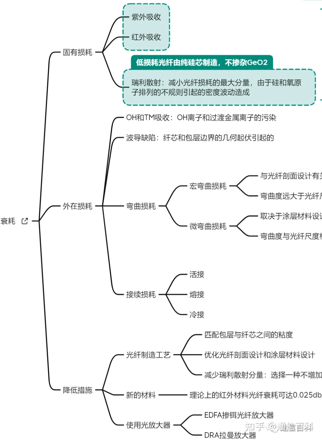
Starting from attenuation, fiber loss can be summarized into two broad categories: one is the fiber’s own intrinsic loss, including Rayleigh scattering, infrared absorption, and ultraviolet absorption; the other is extrinsic loss, including absorption caused by OH ions and TM (transition metals), scattering caused by waveguide defects, and loss caused by fiber bending effects.
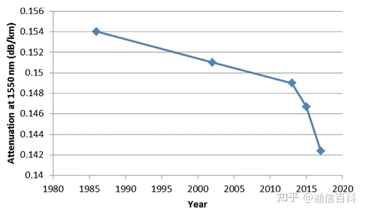
Ever since 1986, when people proposed using pure-silica-core fiber to make low-loss fiber, scientists have racked their brains to push the attenuation down. The following is the fiber loss trend in recent years.
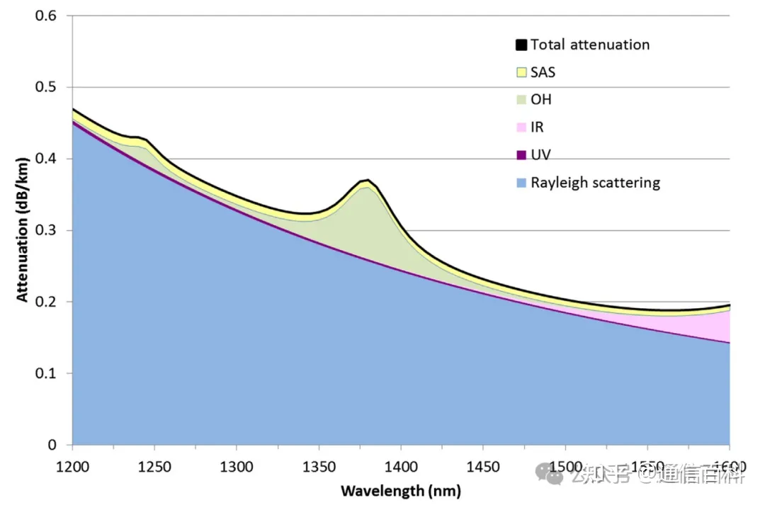
However, to reduce fiber loss, a higher purification process is needed, for example by using a pure-silica core material design. It was also found that Rayleigh scattering is an important factor in reducing fiber loss. That is to say, the greatest opportunity for reducing fiber loss lies in dealing with Rayleigh scattering. This involves processing the atomic distribution of the silicon dioxide in the fiber.
Most fiber deployed today is G.652D. The loss of ultra-low-loss G.652D is around 0.175 dB/km, while ultra-low-loss commercial G.654E is around 0.165 dB/km. It can be seen that over a distance of 100 km, G.654E is less than 1 dB better than G.652 fiber. Over the tens or hundreds of kilometers of a metro network, considering cost factors, G.654E is not cost-effective.
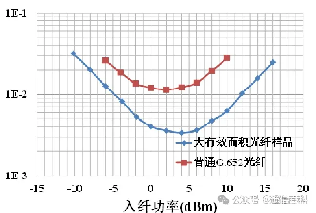
In addition, to transmit farther, the launched optical power can also be raised. Although in high-rate coherent communication the baud rate has increased from 64 Gbd to 90 Gbd, and even to 130 Gbd and above — meaning a larger launched power is allowed — the relationship between launched power and OSNR is not linear. As the power increases, more severe nonlinear effects arise, ultimately degrading the signal.
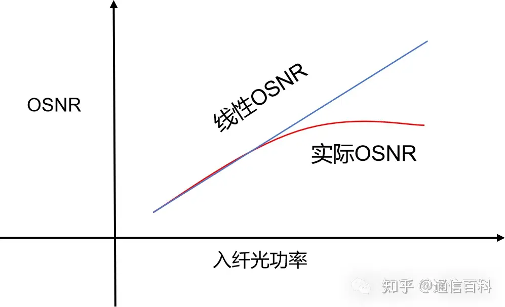
The reason is that, when the effective area of the fiber is fixed, the power density per unit area increases with the power, producing very severe nonlinear effects. Reference: What Are the Nonlinear Effects in Optical Fiber?Once a certain upper limit is exceeded, the OSNR does not increase with power.
The nonlinearity of the fiber is described by its nonlinear coefficient, given by the formula below:

Where Aeff is the effective area of the fiber and n2 is the nonlinear refractive index. Since the nonlinear refractive index of the fiber does not change much, from the fiber’s perspective the only way to reduce the nonlinear coefficient is to increase the fiber’s effective area.
And what parameter of the fiber is the large effective area related to? Right — it is the mode field diameter, MFD.

Here MFD is the mode field diameter. The unit of Aeff is μm². Usually, for more intuitive display, the effective area Aeff is directly used to express the fiber’s anti-nonlinearity indicator. The effective area of our existing G.652D fiber is about 80 μm². The typical effective area value of G.654E described by ITU-T is 110-125 μm².
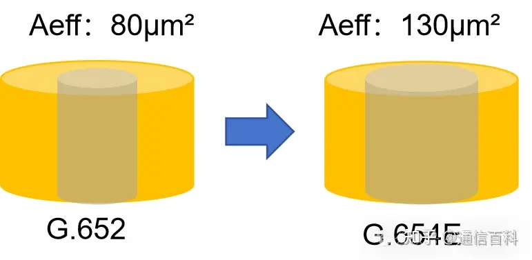
In fact, some manufacturers have already made the effective area of G.654E fiber up to 130 μm². Based on empirical data, compared with G.652D fiber, under the same conditions the launched optical power can be raised by about 2 dB.
So G.654E is now recommended for use in long-haul backbone networks, claimed to be the first choice for long-distance high-speed transmission. If we remain based on the original C-band, especially the C++ band (1524.3 nm-1572.27 nm), and simply replace the G.652D fiber, or newly deploy G.654E fiber, besides the cost we have to consider at least two issues: one is the cutoff wavelength of G.654E to guarantee single-mode transmission, and the other is the inevitable splicing loss with G.652D.
For G.654E fiber, to achieve single-mode transmission in the C++ and even the currently hot C+++L++ systems, the transmission wavelength must be greater than 1530 nm, because the cutoff wavelength of G.654E is 1530 nm. Wavelengths below this value no longer transmit in single mode in 654E fiber. That is to say, keeping the equipment unchanged and directly replacing the G.652D fiber, the wavelengths between 1524.3 nm and 1530 nm cannot be used. Why can G.652 do it? The cutoff wavelength of G.652 is 1260 nm, so this problem does not exist.
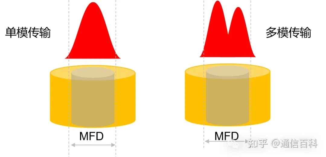
In addition, when splicing with the G.652 fiber of an existing line, the splicing loss needs to be considered. For two different types of fiber, according to the above, the MFD mode field diameters of different fiber types are different. The loss of their splicing can be calculated by the following formula:

Download:
Ultra-Strong Ultra-Low-Attenuation Large-Effective-Area Single-Mode Fiber 654E
Research on the Long-Distance Transmission Performance of G.654.E Fiber
Ultra-Low-Loss G.654E Optical Fiber
Related Reading
- What Is the Transmission Path of Light in an Optical Fiber?
- Optical Fiber Communication: The Structure of Optical Fiber
- Optical Fiber Communication: Mode Field Diameter and Cutoff Wavelength
Enjoy this article?
Subscribe to get new optical communication insights delivered to your inbox. Free, unsubscribe anytime.