
In the previous article “Dielectric Thin-Film Filter (TFF)“, we discussed the multiplexing and demultiplexing function of the dielectric thin-film filter TFF in WDM systems. Today, we will explore in depth another important device that also has such functions – the Fiber Bragg Grating (FBG).
The internal structure of an ordinary optical fiber is mainly composed of a core and a cladding, where the refractive index of the core is slightly greater than that of the cladding, ensuring total internal reflection of light within the core under appropriate conditions.

We know that light can propagate in the fiber essentially because we artificially construct a refractive index difference between the core and the cladding, so that when light enters the fiber at a certain angle, total internal reflection occurs. In fact, light of different wavelengths behaves differently at a specific refractive index ratio; part of the light will refract into the cladding rather than all remaining within the core.

This is because the optical wavelength is a range value; at a certain refractive index ratio, some wavelengths refract and some reflect.
So, can we design a fiber that can selectively reflect light of a specific wavelength while transmitting (refracting) light of other wavelengths?
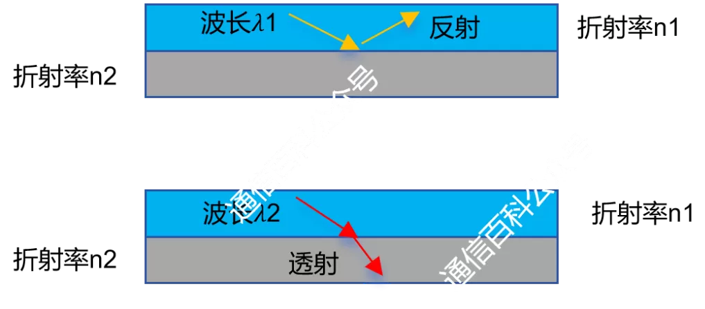
Of course we can. This is the Fiber Bragg Grating (FBG). That is, by periodically modulating the refractive index of the fiber core, light of a specific wavelength is reflected in the fiber, thereby filtering out a specific optical signal and transmitting light of other wavelengths. This brings us to today’s protagonist – the Fiber Bragg Grating.
The Bragg grating looks like this (schematic diagram).

The grating period here (the distance between two adjacent refractive index modulation units) is specifically designed. When the grating period is about half the wavelength of the incident light, all reflected light coherently combines into a strong reflection of a specific wavelength. Expressed as a formula: 2n·Lambda = lambdaBragg, where n is the effective refractive index; Lambda is the period of the fiber Bragg grating, that is, the interval length between two adjacent refractive index changes; lambdaBragg is the wavelength of the reflected light, that is, the Bragg wavelength.
For intuitive presentation, let us take a section (one-dimensional) of the Bragg grating from the schematic diagram above, as follows.

We can use an “optical sieve” to describe the fiber Bragg grating, selectively letting light of a specific wavelength (that is, with the appropriate “particle size”) be “stuck” on the grating structure to achieve reflection or transmission. The fiber Bragg grating filter uses this principle, working with a circulator or other isolation components in DWDM systems as a multiplexer/demultiplexer or wavelength add/drop.


At this time, the grating period Lambda is uniform. Similar to the filter made in the previous article “Dielectric Thin-Film Filter (TFF)“, but there are significant differences between the two.

In a thin film, the refractive index change of the filter is discontinuous. In a Bragg grating, the refractive index change is continuous and much smaller. Another difference from when the dielectric thin film is used as a filter: the dielectric thin-film filter reflects all wavelengths, as shown below, whereas the fiber Bragg grating reflects waves of a distinct wavelength and transmits other waves (as in the previous previous figure).
In the filters above, including when fiber grating is used to make a GFF, the grating period Lambda is uniform. Of course, the length of this period Lambda can be uniform or non-uniform. For example, when a Bragg fiber grating is used for dispersion compensation, the grating periods have different spacings.
In addition, the refractive index n and the grating period Lambda are also affected by temperature and strain. Therefore, an important use of fiber Bragg gratings is to make sensors, such as strain sensing and temperature sensing.
Specifically, as shown in the figure above, when the FBG is stretched or compressed, the fiber deforms accordingly, causing the length of the grating period Lambda to change (increasing when stretched, shortening when compressed). This change in period length affects the Bragg wavelength (lambdaBragg).
Related Reading
- What Is the Propagation Path of Light in Optical Fiber?
- Optical Fiber Communication: The Structure of Optical Fiber
- Optical Fiber Communication: Mode Field Diameter and Cutoff Wavelength
Enjoy this article?
Subscribe to get new optical communication insights delivered to your inbox. Free, unsubscribe anytime.