In the field of silicon photonics, the design and application of optical waveguides often favor the TE mode rather than the TM mode. The reasons behind this choice are multifaceted, involving complex physical phenomena and practical application considerations.
From the two figures below, it can be seen that in the 1550 nm and 1310 nm bands, when the waveguide thickness is below 240 nm and 205 nm respectively, both TE and TM modes can exist. However, at the same thickness, the effective refractive index of the TE mode is always higher than that of the TM mode.
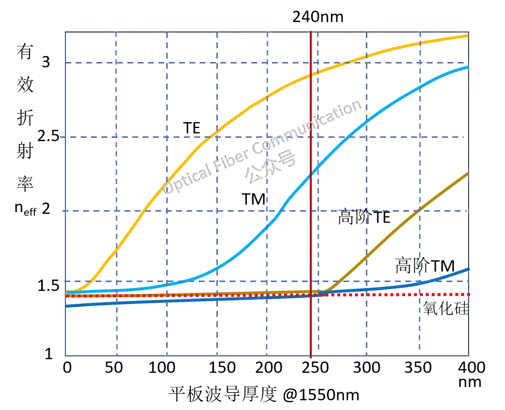
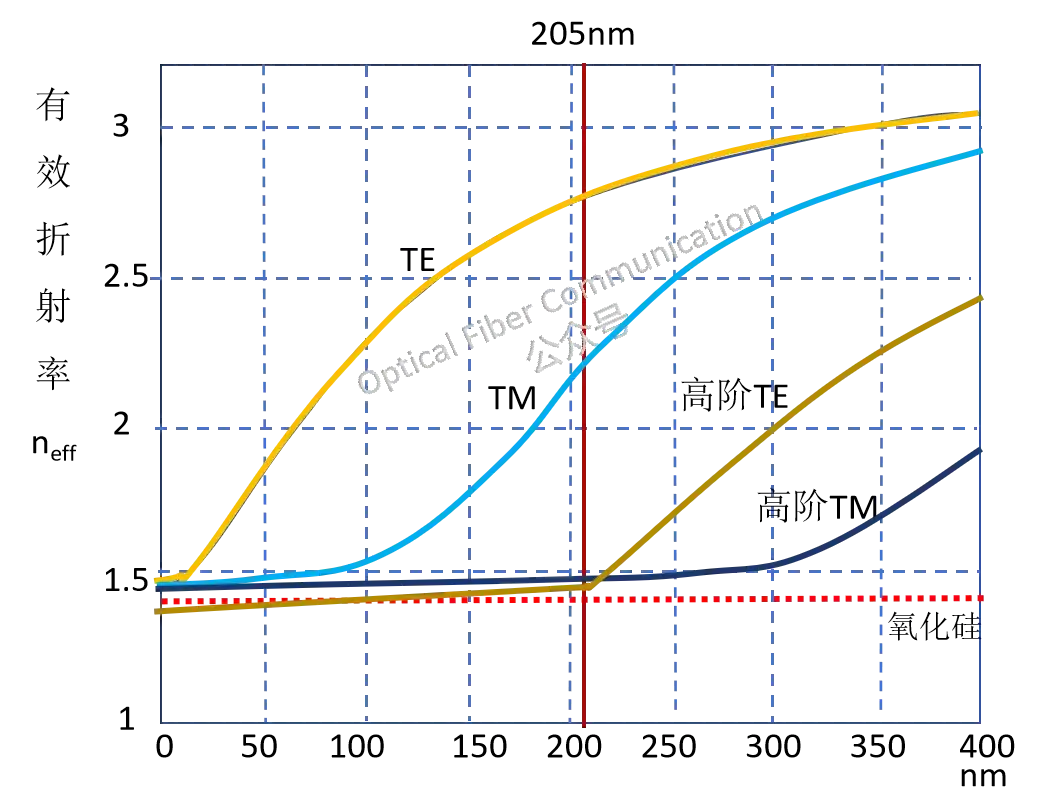
Further analyzing from the confinement capability of the field distribution: this confinement capability refers to how concentrated the optical field is inside the waveguide and how fast it decays outside the waveguide. In theory, the TE mode has stronger confinement due to its field-distribution characteristics, meaning the TE mode’s optical field is more concentrated inside the waveguide and decays faster outside it.
Specifically, the mode effective refractive index neff mentioned above is a key parameter measuring its propagation capability in the waveguide, and it directly affects the mode’s field distribution and propagation characteristics.
In the cladding of the waveguide, the decay of the field intensity can be approximately expressed as an exponential decay form:
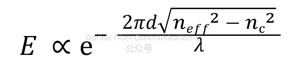
E is the field intensity at a distance d from the core-cladding interface; neff is the effective refractive index of the mode; nc is the refractive index of the cladding. It can be seen that the larger neff is, the larger the difference from the cladding refractive index, meaning the faster the field decays in the cladding.
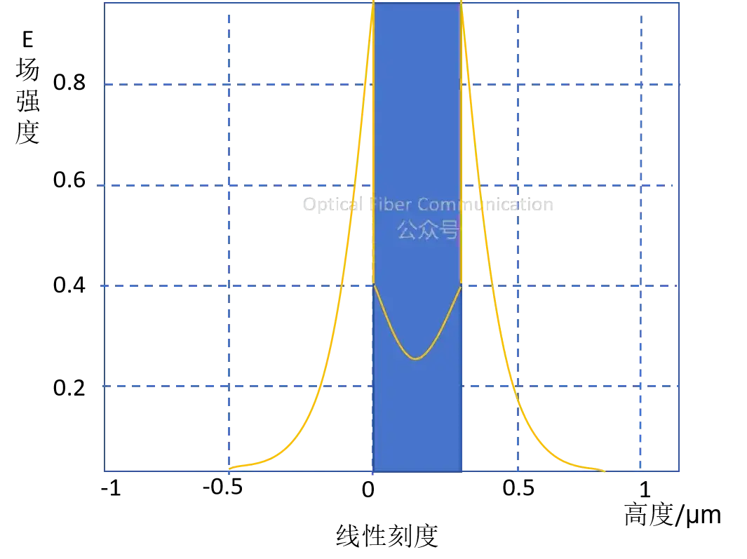
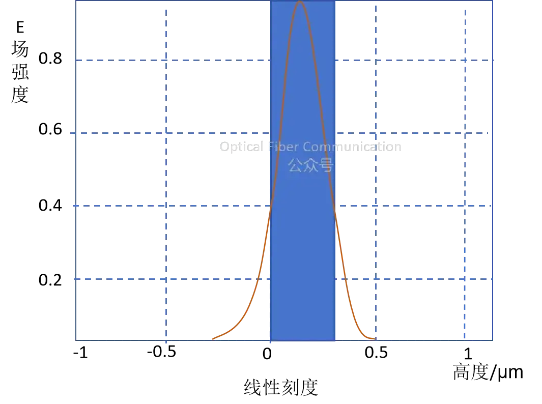
The effective refractive index of the TE mode is 2.845, and the fundamental mode (TE) distribution of the planar waveguide is shown below:
The effective refractive index of the TM mode is 2.845, and the second-order mode (TM) distribution of the planar waveguide is shown below:
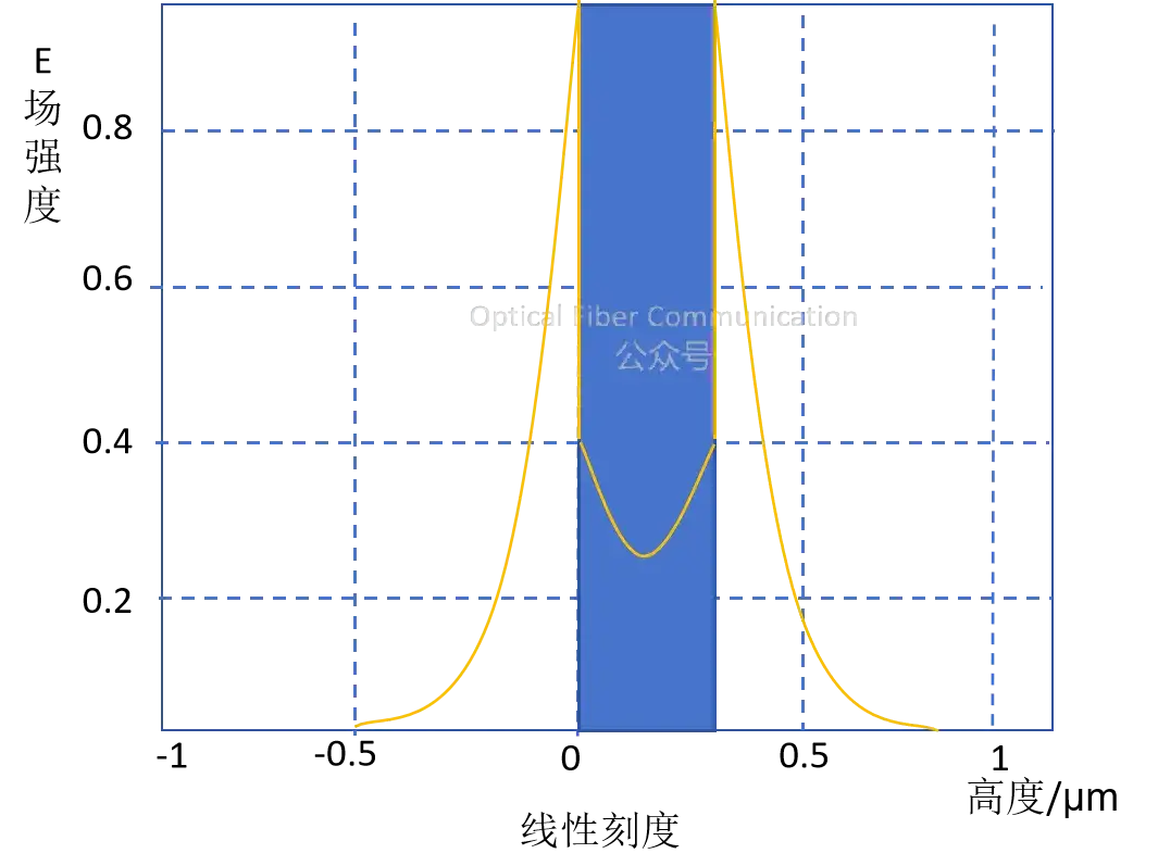
It can be seen that the mode with a higher effective refractive index is better confined inside the waveguide, while its evanescent-field tail outside the waveguide decays faster. Compared with the TM mode, the TE mode, due to its higher effective refractive index, obtains better field confinement. This makes the TE mode have lower propagation loss in waveguides with high refractive-index contrast and tight mode confinement, and it is also conducive to reducing the mode size, making it more suitable for long-distance transmission and high-density-integration photonic device applications.
From the perspective of bending loss, in highly confining strip waveguides, the TE mode usually exhibits lower radiation loss due to its electric-field-distribution characteristics. However, when it comes to ridge waveguides with small bending radii, the radiation loss of the TM mode is relatively high, especially when the bending radius is less than 5 micrometers, where this loss becomes significant. This is mainly because the magnetic field of the TM mode is stronger near the waveguide boundary, making it easier to radiate energy outward at bends.

Therefore, through appropriate design, we can create a structure that only allows TE-mode propagation while blocking TM-mode transmission, and this design acts like a polarization filter.
Thank you for reading. If there are any inaccurate statements, please forgive me and leave a comment to point them out. Thank you!
Related Reading
- Silicon Photonics Series 1: How to Smoothly Couple Light from Fiber into the Waveguide?
- Silicon Photonic Waveguides: How to Ensure Light Polarization at the Receiving End?
- Using Silicon Photonic Modules as a Guinea Pig?
Enjoy this article?
Subscribe to get new optical communication insights delivered to your inbox. Free, unsubscribe anytime.