We mentioned in the previous article that ARF (antiresonant fiber) has two types: tubular and nested. Also, the initially designed hollow-core fiber had many nodes inside, leading to node loss.
In the tubular type, we used a core boundary with negative curvature to eliminate the undesirable nodes, placing them at positions with lower mode field intensity, thereby reducing the attenuation coefficient.

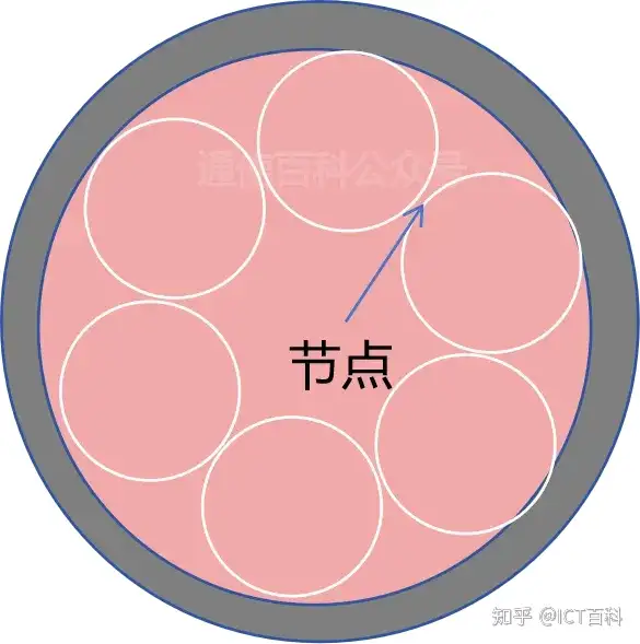
Then, Kolyadin et al. proposed a further improvement, constructing the hollow-core fiber structure by surrounding the core with non-contacting tube rings – this is what we call HC-ANF fiber, abbreviated as ANF fiber.
ANF can be considered an improved version of ARF, further optimizing the cladding structure to eliminate nodes in the cladding.
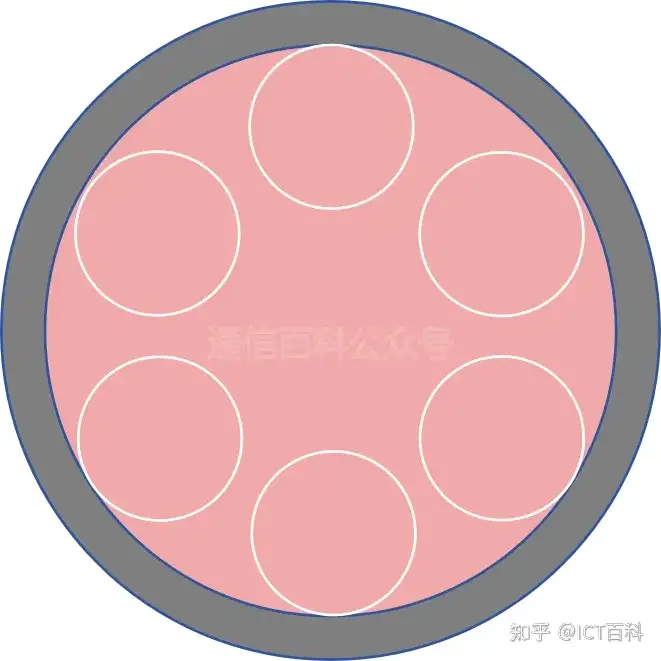
The tubes are spaced a certain distance apart along the azimuthal angle. Light can be confined to a specific region of the fiber, mainly relying on the double Fresnel reflection effect occurring between the inner and outer surfaces of the thin-walled glass tubes surrounding the core.
In this way, the nodes near the core are completely eliminated, and the attenuation coefficient is further reduced compared with similar fibers having contacting nodes.
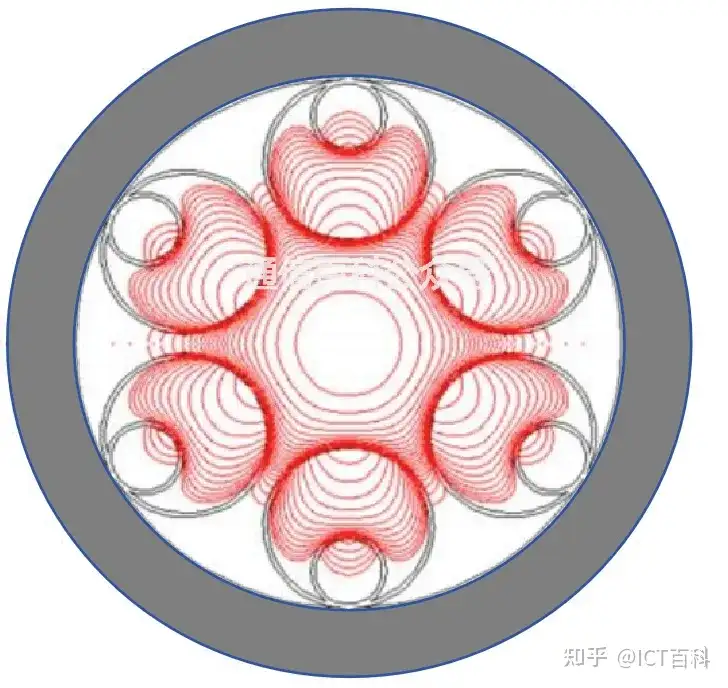
The distribution of the fundamental mode field intensity is shown below, but nodes still exist at the mode field positions.
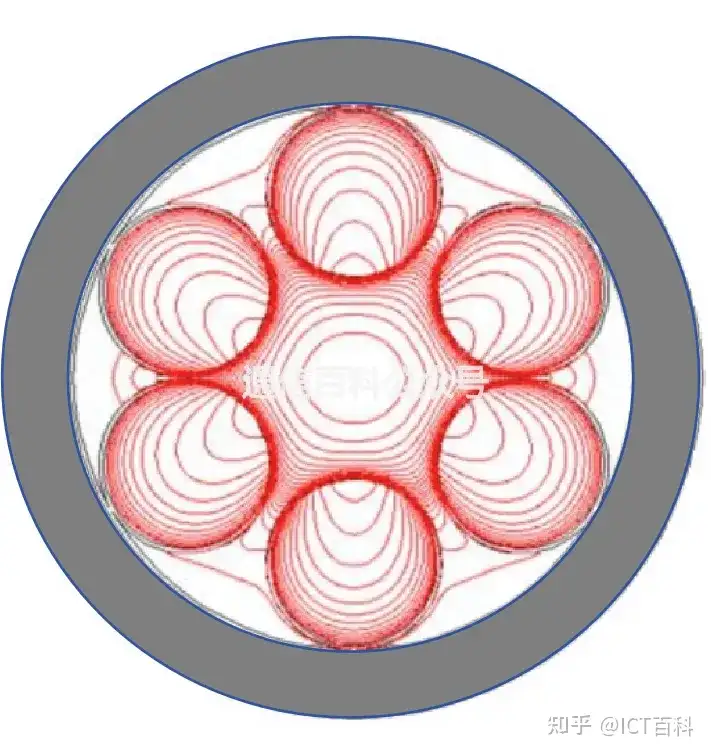
HC-ANF
Next, an improved antiresonant fiber was proposed, by adding one or more nested tubes of the same thickness as the outer tubes and attaching them to the cladding at the same azimuthal positions as the outer tubes.
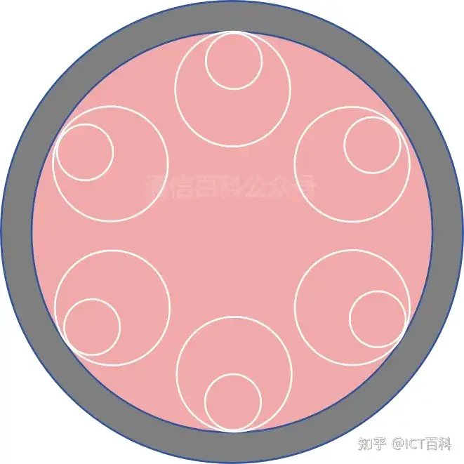
The outer and inner tubes are separated by a certain distance in the direction toward the core.
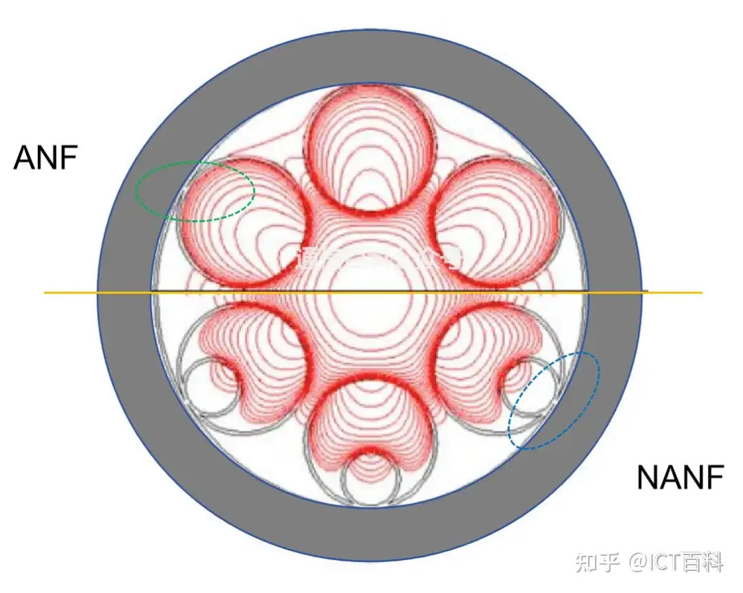
The mode field distribution formed by this type of hollow-core fiber is shown below, with the nodes in the mode field range eliminated. This type of fiber is called hollow-core nodeless antiresonant fiber (HC-NANF), abbreviated as NANF.
HC-NANF
Compared with HC-ANF, because the mode field on the NANF outer cladding basically no longer contacts the outer cladding, its mode field intensity drops from 6 orders of magnitude below the maximum to more than 8 orders of magnitude below.
The figure below is the loss comparison of these two types of fiber at a core radius R = 15um and tube wall thickness t = 0.42um.
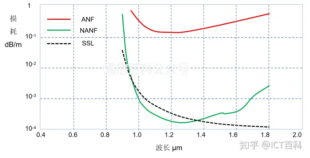
Here, the dashed line represents the surface scattering loss (SSL) of ANF at the air-glass interface, and the value for NANF is the same as that of ANF.
Research has found that fiber with 6 nested tubes performs somewhat better than ANF fiber with 8 or 10 nested tubes.
In principle, the number of resonant nested tubes can be further reduced, that is, to fewer than 6. NANF with 5 nested tubes was reported at OFC, with a core diameter D = 34.5um and a loss of 0.22 dB/km @1060nm.
We will come back specifically to the comparison of the performance of NANF fibers with different numbers of nested layers.
Thanks for reading!
Hollow-Core Fiber 5: How Does Mode Coupling in HCF Affect Loss?
Hollow-Core Fiber 4: Leakage Loss of HCF
Related Reading
- Revealed: What Is Hollow-Core Fiber?
- Hollow-Core Fiber – What Is Photonic Bandgap Fiber?
- Hollow-Core Fiber 7: How to Reduce Surface Mode Loss?
Enjoy this article?
Subscribe to get new optical communication insights delivered to your inbox. Free, unsubscribe anytime.