The InfiniBand network architecture can be used to avoid some of the shortcomings of the PCI bus:
- 1. Because of the bus-based shared transmission mode, more than two sets of data cannot be transmitted simultaneously on the PCI bus. When one PCI device occupies the bus, other devices can only wait;
- 2. As the bus frequency increases from 33MHz to 66MHz, and even 133MHz (PCI-X), the mutual interference between signal lines becomes increasingly serious, and the difficulty of laying out multiple buses on one motherboard also increases;
- 3. Because PCI devices use memory-mapped I/O addresses to establish connections with memory, hot-adding PCI devices becomes a very difficult task. The current approach is to allocate a 50M to 100M area in memory for each PCI device, which users cannot use. Therefore, the more hot-swappable PCI interfaces a motherboard supports, the more memory users lose;
- 4. Although the PCI bus has buffers as data buffers, it does not have error correction capability. If data loss or corruption occurs during transmission, the controller can only trigger an NMI interrupt to notify the operating system that an error occurred on the PCI bus;
Infiniband Protocol Layers and Network Structure
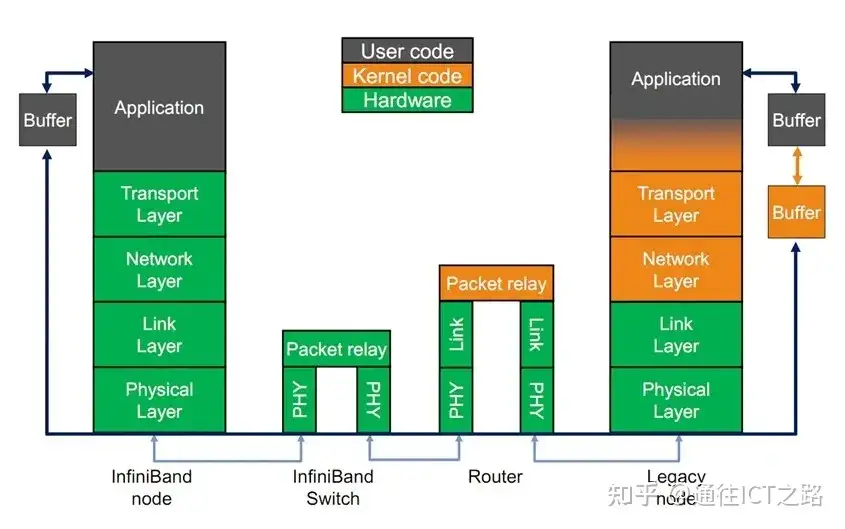
The Infiniband protocol adopts a layered structure, with each layer independent of the others, and the lower layers provide services to the upper layers. The physical layer defines how bit signals are grouped into symbols on the line, then into frames, data symbols, and data padding between packets, detailing the signaling protocol for constructing valid packets; the link layer defines the format of data packets and the protocols for packet operations, such as flow control, routing, encoding, and decoding; the network layer performs routing selection by adding a 40-byte Global Route Header (GRH) to the data packet and forwards the data.
During forwarding, the router only performs variable CRC checks, which ensures the integrity of end-to-end data transmission; the transport layer then delivers the data packet to a specified Queue Pair (QP) and instructs the QP how to handle the packet, as well as segmenting and reassembling the data when the payload portion of the message is larger than the channel’s maximum transmission unit (MTU).
InfiniBand network layer architecture
- Physical layer: defines electrical and mechanical characteristics, including cables and sockets for optical fiber and copper media, backplane connectors, hot-swap characteristics, etc. Defines three types of physical ports: backplane, cable, and optical cable.
- Link layer: describes the format of data packets and the protocols for packet operations, such as flow control and routing of packets within the subnet. The link layer has two types of packets: link management packets and data packets.
- Network layer: the protocol for forwarding data packets between subnets, similar to the network layer in IP networks. It implements data routing between subnets, and data transmitted within a subnet does not require network layer participation.
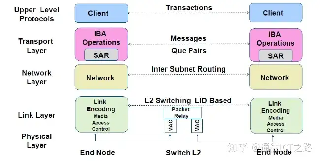
- Transport layer: responsible for packet distribution, channel multiplexing, basic transport services, and handling the sending, receiving, and reassembly of message segments. The function of the transport layer is to deliver data packets to each specified queue (QP) and instruct the queue how to handle the packets. When the data path load of a message is larger than the maximum transmission unit (MTU) of the path, the transport layer is responsible for splitting the message into multiple data packets.
- Upper-layer network protocols: InfiniBand provides different upper-layer protocols for different types of users, providing a Verbs interface between applications and hardware drivers, allowing upper-layer applications to perform RDMA programming based on the Verbs interface; and defines messages and protocols for certain management functions. InfiniBand mainly supports upper-layer protocols such as SDP, SRP, iSER, RDS, IPoIB, and uDAPL.
Infiniband Network Topology
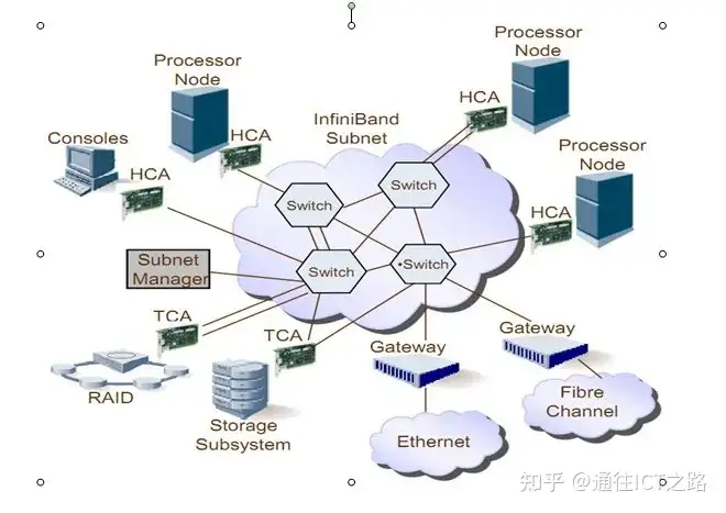
The network topology of Infiniband is shown in the figure, and its constituent units are mainly divided into four categories:
- (1) HCA (Host Channel Adapter), which is the bridge connecting the memory controller and the TCA;
- (2) TCA (Target Channel Adapter), which packages the digital signals of I/O devices (such as network cards and SCSI controllers) and sends them to the HCA;
- (3) Infiniband link, which is the optical fiber connecting HCA and TCA. The InfiniBand architecture allows hardware vendors to connect TCA and HCA in three ways: 1, 4, or 12 optical fibers;
- (4) Switches and routers;
Whether it is HCA or TCA, it is essentially a host adapter, a programmable DMA (Direct Memory Access) engine with certain protection functions.
Omni-Path continues to use the True Scale product name and technology (acquired QLogic’s InfiniPath network product line and renamed it True Scale), with the main change being raising the physical layer speed from 40G to 100G. To be compatible with more open-source systems, Omni-Path is also based on the open-source standard OFED architecture (Mellanox also adopts this framework) and opens its API interface.
Intel has integrated Omni-Path-related functions into the CPU, which means Omni-Path is more efficient in communication, but it makes the network dependent on the CPU, and at least in terms of processors, its openness is still relatively limited.
By acquiring Cray’s interconnect division, Intel introduced the concept of layer 1.5 in Omni-Path. It is called the Link Transport Layer, based on Cray’s Aries basic interconnect technology to optimize underlying data communication, providing reliable layer-2 packet delivery, flow control, and single-link control. This also fully utilizes the acquired Cray Aries technology.
OPA components
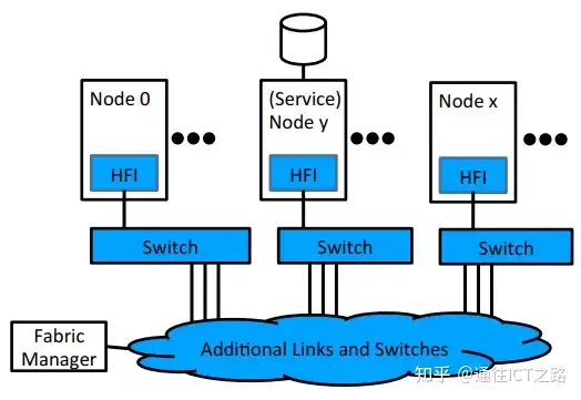
Omni-Path mainly has the following three components:
- HFI – Host Fabric Interface, providing fiber connection for host, service, and management nodes
- Switches, providing arbitrary topology connections between nodes at scale
- Fabric Manager, providing centralized provisioning and monitoring of fabric resources
Compared with InfiniBand, the design goal characteristics of Intel Omni-Path Architecture are:
- Improve cost, power, and density through CPU/Fabric integration
- Optimized host-side implementation for high-speed MPI messages, low-latency, high-scalability architecture
- Enhanced Fabric Architecture to provide ultra-low end-to-end latency, efficient error correction and enhanced QoS, and ultra-high scalability
RDMA technology
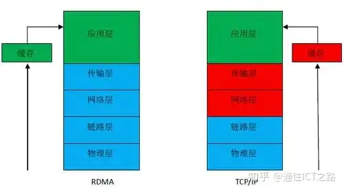
The biggest breakthrough of RDMA technology is placing the network layer and transport layer in hardware, implemented on the server’s network card. After a data packet enters the network card, the four-layer parsing is completed on the network card hardware, and it is directly sent up to the application layer software, with no CPU intervention needed for the four-layer parsing.
The full name of RDMA technology is Remote Direct Memory Access, which was created to solve the delay of server-side data processing in network transmission. RDMA transfers data directly into the server’s storage area through the network card without affecting the operating system, eliminating external memory copying and text exchange operations, freeing memory bandwidth and CPU resources. When an application executes an RDMA read or write request, no data copying is performed.
Without any kernel memory participation, RDMA requests are sent from applications running in user space to the local network card, and then transmitted over the network to the remote server’s network card. RDMA was originally exclusive to the Infiniband architecture, and with the trend of network convergence, RoCE (RDMA over Converged Ethernet) and iWARP (RDMA over TCP/IP) emerged, allowing RDMA with high speed, ultra-low latency, and extremely low CPU usage to be deployed on the most widely used data center networks today.
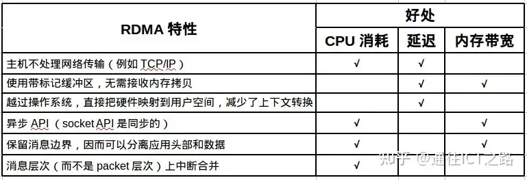
Specifically, the benefits brought by the technical characteristics of RDMA are shown in the figure below:
NVMe devices have very low latency, which requires network latency to also be very low, and RDMA satisfies exactly this point.
Take an NVMe write operation as an example. The NVMe host driver encapsulates the write command and data (taking an item from the NVMe submission queue) into a command capsule that is independent of the underlying transport; the capsule is placed into the send queue of the host RDMA network card and sent out via RDMA_SEND; the RDMA network card of the target host receives this capsule in the receive queue, decapsulates it, and places the NVMe command and data into the target host’s memory; the target host processes the NVMe command and data; after completion, the target host encapsulates an NVMe command completion item and transmits it to the source host via RDMA.
Two RDMA protocols based on Ethernet
First: Ethernet -> IP -> UDP -> RoCE (RDMA over Converged Ethernet) v2
Second: Ethernet -> IP -> TCP (removing TCP/IP flow control and management) -> iWARP
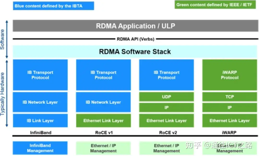
InfiniBand listed alongside RoCE and iWARP
InfiniBand adopts the Cut-Through forwarding mode to reduce forwarding latency, based on the Credit flow control mechanism to ensure no packet loss. RoCE’s performance is comparable to IB networks, and DCB characteristics ensure no packet loss, requiring the network to support DCB characteristics, but its latency is slightly higher than IB switches. iWARP utilizes mature IP networks and inherits the advantages of RDMA, but packet loss on traditional IP networks has a large impact on performance.

The main problem of iWARP technology lies in stability. Once there is packet loss on the network, the performance will be extremely poor. And iWARP is implemented based on the Ethernet protocol, which cannot avoid packet loss, making iWARP technology lose its application space.
IB has the best performance, while RoCE is used the most. RoCE became popular along with RDMA technology. Compared with IB technology, RoCE is still implemented based on Ethernet, but adds a packet loss control mechanism to ensure Ethernet is in a lossless state. Although its latency is slightly worse than IB, its deployment cost is much lower.
Analyzing the RDMA over TCP (iWARP) Protocol Stack and Working Principle
For devices equipped with RNIC (RDMA-aware network interface controller) network cards, whether it is the target device or the source device, the host processor does not participate in data transmission operations. The RNIC network card is responsible for generating RDMA packets and receiving incoming RDMA packets, thereby eliminating redundant memory copy operations in traditional operations.
The RDMA protocol provides the following four data transfer operations (RDMA Send operation, RDMA Write operation, RDMA Read operation, and Terminate operation). Except for the RDMA read operation, which does not generate an RDMA message, all other operations generate an RDMA message.
Ethernet, with its advantages of low investment, backward compatibility, easy upgrade, and low operating cost, occupies a dominant position in the current network interconnect field. The current mainstream Ethernet rates are 100 Mb/s and 1000 Mb/s, and the next-generation Ethernet rate will be upgraded to 10Gb/s. Adding RDMA characteristics to Ethernet will reduce host processor utilization, increase the advantages of upgrading Ethernet to 10 Gb/s, eliminate the drawback of the huge overhead introduced by upgrading to 10 Gb/s, and allow data centers to expand their structure without affecting overall performance, providing sufficient flexibility for future expansion needs.
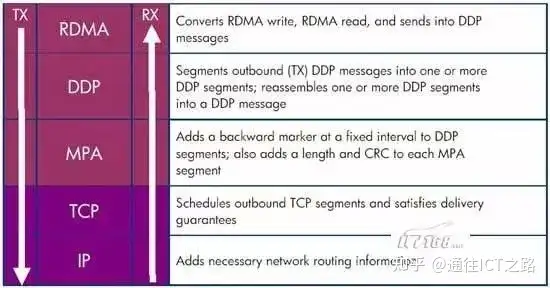
RDMA over TCP (Ethernet) protocol stack
The figure above is the protocol stack of RDMA over TCP (Ethernet). The top three layers constitute the iWARP protocol family, used to ensure the interoperability of high-speed networks.
The RDMA layer protocol is responsible for converting RDMA write operations and RDMA read operations into RDMA messages, and transmitting the RDMA messages to the Direct Data Placement (DDP) layer.
The DDP layer protocol is responsible for segmenting overly long RDMA messages into DDP packets and continuing to forward them down to the Marker-based, Protocol-data-unit-Aligned (MPA) layer.
The MPA layer adds a backward marker, length, and CRC check data at fixed intervals of the DDP data segment to form the MPA data segment.
The TCP layer is responsible for scheduling TCP data segments to ensure that packets can smoothly reach the target location.
The IP layer adds the necessary network routing data information to the data packet.
The transport interface layer (Software Transport Interface) between RDMA applications and the RNIC (RDMA-aware Network Interface Controller) is called Verbs or the RDMA API. The RDMA API (Verbs) mainly has two types of Verbs:
- Memory Verbs, also called One-Sided RDMA. Including RDMA Reads, RDMA Writes, RDMA Atomic. In this mode, RDMA access does not require any confirmation from the remote machine.
- Messaging Verbs, also called Two-Sided RDMA. Including RDMA Send, RDMA Receive. In this mode, RDMA access requires the participation of the remote machine’s CPU.
IB, Ethernet RoCE, and Ethernet iWARP, these three RDMA technologies use a unified API.
Upper-layer protocols
InfiniBand provides different upper-layer protocols for different types of users, and defines messages and protocols for certain management functions. InfiniBand mainly supports upper-layer protocols such as SDP, SRP, iSER, RDS, IPoIB, and uDAPL.
- SDP (Sockets Direct Protocol) is a protocol based on InfiniBand formulated by the InfiniBand Trade Association (IBTA), which allows existing programs using the TCP/IP protocol to run on high-speed InfiniBand.
- SRP (SCSI RDMA Protocol) is a communication protocol in InfiniBand that packages SCSI commands in InfiniBand, allowing SCSI commands to communicate between different systems through RDMA (Remote Direct Memory Access), realizing storage device sharing and RDMA communication services.
- iSER (iSCSI RDMA Protocol) is similar to the SRP (SCSI RDMA Protocol) and is a protocol of IB SAN. Its main role is to run iSCSI protocol commands and data over networks such as InfiniBand through RDMA. As an iSCSI RDMA storage protocol, iSER has been standardized by the IETF.
- RDS (Reliable Datagram Sockets) protocol is similar to UDP and is designed for sending and receiving data using sockets on InfiniBand. It is actually a protocol developed by Oracle running on InfiniBand, directly based on IPC.
- IPoIB (IP-over-IB) is a protocol formulated to achieve compatibility between INFINIBAND networks and TCP/IP networks. Based on the TCP/IP protocol, it is transparent to user applications and can provide greater bandwidth, meaning applications originally using the TCP/IP protocol stack can use IPoIB without any modification.
- uDAPL (User Direct Access Programming Library) is a standard API that improves the performance, scalability, and reliability of data message transfer in data center applications through interconnects with Remote Direct Memory Access RDMA functionality (such as InfiniBand).
Among them, IPoIB
IPoIB (IP-over-IB) is a protocol formulated to achieve compatibility between INFINIBAND networks and TCP/IP networks. Based on the TCP/IP protocol, it is transparent to user applications and can provide greater bandwidth, meaning applications originally using the TCP/IP protocol stack can use IPoIB without any modification.
The role of IPoIB is to provide an IP network emulation layer on top of the InfiniBand RDMA network.
Because iWARP and RoCE/IBoE networks are actually RDMA-based IP networks, they do not need IPoIB. Therefore, the kernel will refuse to create any IPoIB devices on top of iWARP or RoCE/IBoE RDMA devices.
IPoIB limitations
- IPoIB solves many problems for us. However, compared with standard Ethernet network interfaces, it has some limitations:
- IPoIB only supports IP-based applications (because the Ethernet header is not encapsulated).
- SM/SA must be available at all times for IPoIB to function.
- The MAC address of the IPoIB network interface is 20 bytes.
- The MAC address of the network interface cannot be controlled by the user.
- The MAC address of the IPoIB network interface may change during consecutive loads of the IPoIB module, and it is not persistent (that is, a constant attribute of the interface).
- Configuring VLANs on an IPoIB network interface requires understanding the SM of the corresponding p_key.
Related Reading
- Ethernet and Optical Transmission – FlexE (2)
- Introduction to 400G Ethernet Transceivers
- Flexible Ethernet (FlexE) Link Interface Test Method (YD_T 3992-2021)
Enjoy this article?
Subscribe to get new optical communication insights delivered to your inbox. Free, unsubscribe anytime.