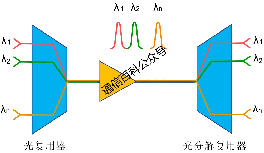
This article is mainly written for the designers and planners of DWDM networks, because they need to estimate the optical power levels at various input and output points across the entire link, span, or network. This information is very important for actual deployment or commissioning.
Ideally, we hope that the theoretical values and actual values can match very well with minimal deviation, and that the system remains balanced in terms of power values. Otherwise, debugging the network and determining the cause of the imbalance will make the deployment and commissioning of the entire network very difficult. Before we officially begin, let us first understand what DWDM is, which has been mentioned many times in our previous articles.
Introduction to DWDM
DWDM is a fiber-based technology that carries different communication channels by multiplexing multiple wavelengths within the optical fiber (each wavelength is a channel). This method of using multiple virtual fiber channels on a single physical fiber provides a more cost-effective solution compared with SDH, saving resources by reducing the need for optical cables and expensive equipment.
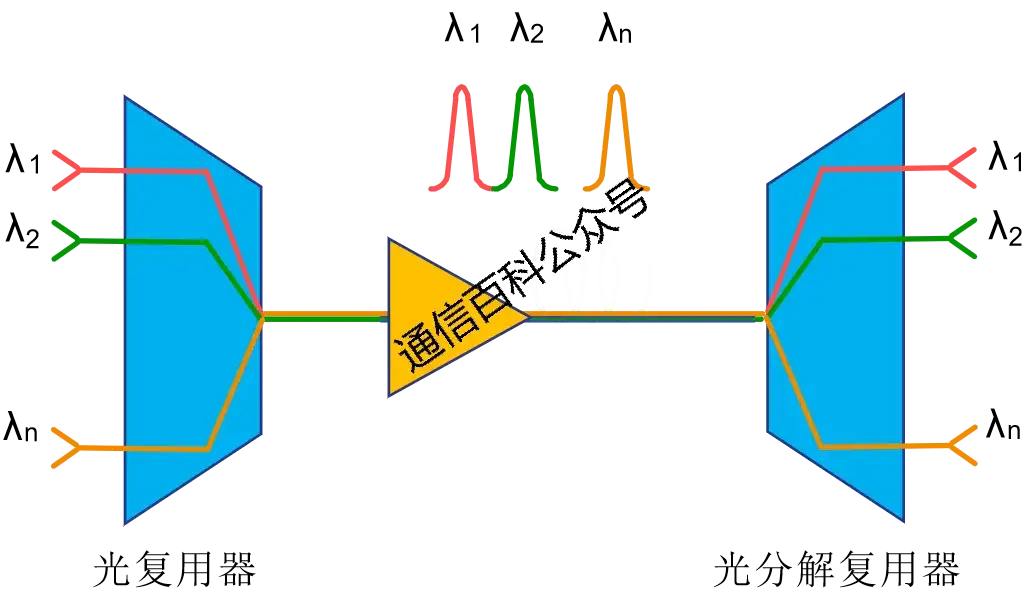
Figure 1
DWDM uses a multiplexer (Mux) at the transmitting end and a demultiplexer (DeMux) at the receiving end, as well as optical amplifiers in between, which have various types and saturated output and gain values.
At the same time, the input and output of a DWDM system usually require optical transponders, because the ingress signals usually come from client signals such as SDH, and the channel wavelength needs to be converted from the standard SDH wavelength (1,310 nm or 1,550 nm) to the operating band used by the DWDM system. As shown in the figure below:
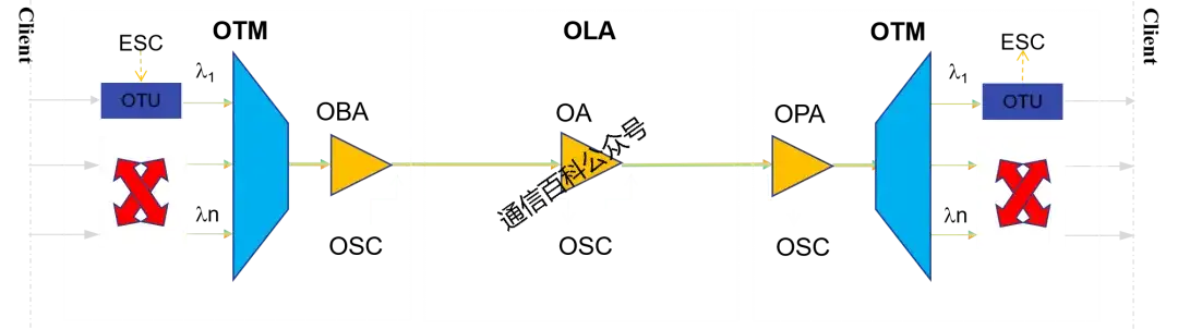
Figure 2
At the same time, the reverse process is performed at the end of the link to restore the original wavelength, which then enters the SDH equipment. Most components of a DWDM system are passive (requiring no external power supply or electronic circuits), making DWDM systems more cost-effective compared with SDH.
What is optical power balancing?
As mentioned above, an important task of DWDM network designers/planners is to estimate the optical power values at each entry/exit point of the system, and to propose a theoretically power-balanced end-to-end system before launch, with only minor adjustments needed during on-site deployment. The closer the calculation is to reality, the easier it is to debug the system during the acceptance testing phase, because the actual values will closely match the estimated values, provided the on-site survey is accurate.
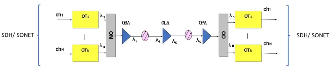
Figure 3
In previous work, I had the privilege of working with experienced designers and planners who made a very accurate design of a system spanning about 2000 km from the south to the north of Pakistan. Before diving deeper, we must understand concepts such as channel power difference, power units, optical amplifier ratings, and the insertion loss of Mux and DeMux.
Channel power difference
A DWDM system is a multi-wave system, meaning multiple waves are transmitted through the fiber. Therefore, the optical power of each wave must be matched. It is recommended to keep the optical power difference between any two wavelengths below 3 dB (there may be smaller difference requirements at the transmitting and receiving ends). Of course, the smaller the difference, the better the result, as this helps avoid the use of complex workarounds.
Power units
dB is the logarithmic ratio between output power and input power.
dB = 10log10 (POUTPUT / PINPUT)
dBm is a physical unit, also called absolute power. It is a measurement of power in decibels using 1 mW as the reference point.
dBm = 10log10 (P / 1 mW)
Optical amplifiers
As shown in Figure 3, the three common types of amplifiers in DWDM system design are the optical booster amplifier (OBA), the optical preamplifier (OPA), and the optical line amplifier (OLA).
Among them, OLA is mainly used for long-distance deployment and can be used in multiple units depending on the fiber length. It helps reduce span loss and improves the noise performance of the transmission line by boosting the optical signal during transmission.
For example, if you see OBA2420, the first two digits (such as 24) indicate the gain of the amplifier in dB, while the last two digits (such as 20) indicate the maximum output power of the amplifier in dBm.
Similarly, for OPA1512, the first two digits (such as 15) indicate the gain of the preamplifier (in dB), and the last two digits (such as 12) indicate the maximum output power of the preamplifier (in dBm).
Insertion loss of Mux and DeMux
Regarding insertion loss, you can watch the video below to understand it:
Science Popularization Alliance, 17 likes
During system commissioning, the insertion loss of the Mux can be calculated using the following formula:
Moutput = 10logPm – Insertion Loss & 10logPm = 10logPi + 10logN ………… {Pm = Pi x N}
Where:
- Moutput = Mux output
- Pm = total multiplexed input power of Mux before insertion loss
- Pi = optical power of each wavelength (from the optical transponder OTU)
- N = number of input wavelengths
Similarly, the insertion loss of the DeMux can be calculated as follows:
Doutput = 10logPm – Insertion Loss
Where:
- Doutput = DeMux output
- Pm = total multiplexed input power of DeMux before insertion loss
Optical power balancing example
For ease of learning, let us calculate the value and position of the attenuator to balance the power in a 32-wavelength system as an example. Currently, the system uses 5 wavelengths (32 in total). Using APD-type receiver sensitivity, it operates optimally at -14 dBm. The output power of the optical transponder OTU is -3 dBm.
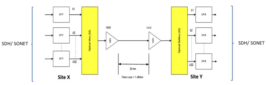
Figure 4
In a system with 32 channels, 5 channels are currently used. The goal is to determine the value and position of the attenuator.
System parameters
- OTU output power: -3 dBm
- Mux insertion loss: 7 dB
- DeMux insertion loss: 7 dB
- OTU receiver sensitivity: -14 dBm
- OBA1620: gain = 16 dB, maximum output power = 20 dBm
- OPA1412: gain = 14 dB, maximum output power = 12 dBm
- Distance between site X and Y: 20 kilometers
- Fiber loss rate: 1 dB/km
Logarithmic calculation
- 10log32 = 15
- 10log5 = 7
Mux calculation
Mux input power:
- Pm = Pi x N or 10logPm = 10logPi + 10logN
- 10logPi = -3 dBm & 10log5 = 7 dBm (N=5)
Therefore, 10logPm = -3+7 = 4 dBm
Mux output power:
- Moutput = 10logPm
Therefore, with insertion loss; Moutput = 4-7 = -3 dB
OBA calculation
- OBA input power:
- OBA input power = maximum output power – gain
- OBA input power = 20 – 16 = 4 dBm
Channel power:
- Power of 32-channel OBA = power of 1-channel OBA + 10log32
- Power of 1-channel OBA = power of 32-channel OBA – 10log32
- Power of 1-channel OBA = 4 – 15 = -11 dBm
- Power of 5-channel OBA = power of 1-channel OBA + 10log5 = -11+7 = -4 dBm
The OBA input needs -4 dBm, while the Mux output provides -3 dBm, so we need an OBA input attenuator with a value of 1 dB.
OPA calculation
- OPA input power = OBA output power – line loss
- OPA input power = 20 – 20 = 0 dBm
- OPA input power = OPA output power – OPA gain = 12 – 14 = -2 dBm
Therefore, the required OPA input power is -2 dBm, but we have 0 dBm, so we need an OPA input attenuator with a value of 2 dB.
OPA output:
This 12 dBm OPA output power applies to 32 channels, so for one channel:
- Power of 32-channel OPA = power of 1-channel OPA + 10log32
- Power of 1-channel OPA = 12 – 15 = -3 dBm
- Power of 5-channel OPA = power of 1-channel OPA + 10log5 = -3+7 = 4 dBm
- DeMux calculation
- DeMux output power = power of 5-channel OPA – insertion loss
- Demultiplexer output power = 4-7 = -3 dBm (for 5 channels)
- DeMux output power (5 channels) = DeMux output power (1 channel) + 10log5
- Demultiplexer output power (1 channel) = -3-7 = -10 dBm
But APD needs -14 dBm, so the solution can be as follows:
Solution
- Solution 1: Insert a 4 dB attenuator at the input of each OTU receiver.
- Solution 2: Insert a 4 dB attenuator at the input of the DeMux.
Recommendation: Solution 2 is better because it eliminates the need for multiple attenuators.
Regarding DWDM/OTN/ROADM/WSON systems, you can study the following courses:
- Course: Principles and Applications of WDM Systems

- Course: ROADM and WSON Technology in OTN

Related Reading
- Transmission Mode of Time Synchronization 1588 in DWDM/OTN
- China Telecom 200G DWDM New Construction Partial Procurement Awarded: ZTE Ranked First
- What Is the Optical Module Solution for 400G DWDM?
Enjoy this article?
Subscribe to get new optical communication insights delivered to your inbox. Free, unsubscribe anytime.