The O-band, that is, the spectral range of 1260-1360 nm, was defined in the mid-1970s, a period when the power loss of optical fiber within the O-band was the lowest.
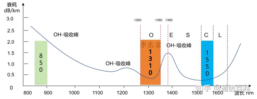
As for its short-wavelength boundary of 1260 nm, we have already discussed it in the previous article “Why 850 nm and 1260 nm?“. Its long-wavelength boundary of 1360 nm is chosen to avoid the OH⁻ (hydroxyl) absorption peak. Traditional optical fiber has a loss peak of up to 1.5 dB/km here.
By adding a coating on the fiber that can block hydrogen penetration, the OH⁻ ion content in the fiber can be significantly reduced (to below 1 ppb), thereby basically eliminating the water absorption peak near 1360 nm. This kind of fiber that meets the low-water-peak requirement (such as the ITU-T G.652.D standard). Of course, this is a matter of the E-band.
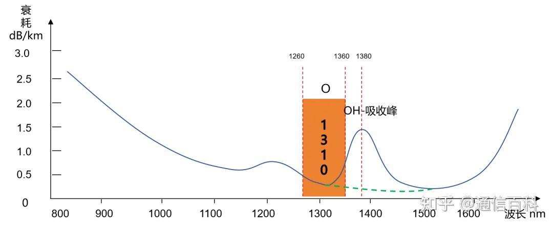
The typical value of fiber at 1310 nm in the O-band is 0.32-0.38 dB/km, mainly caused by Rayleigh scattering, accounting for about 96% of the fiber attenuation. To put it plainly, the fiber cannot achieve ideal uniformity during the manufacturing process, and there are always some fluctuations. For example, fluctuations in glass composition will lead to tiny refractive index changes; and density fluctuations, a fundamental fluctuation that cannot be improved. We will discuss the principle of Rayleigh scattering in later chapters.
In addition to the Rayleigh scattering loss caused by the fiber’s own properties, the O-band must also consider bending loss, including macrobending loss and microbending loss. Especially in the fiber cabling process, microbending caused by improper handling will introduce additional loss. Accordingly, there is the G.657.A1 bend-insensitive fiber, which uses the O-band and is mainly applied to fiber-to-the-home.
From the perspective of macrobending loss resistance, a schematic diagram is given:
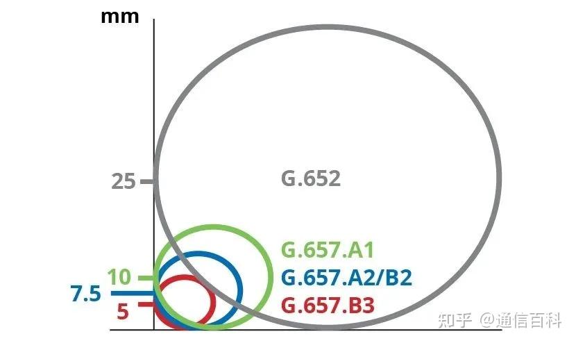
The minimum bending radius of G.657.A1 is 10 mm, that of G.657.A2/B2 is 7.5 mm, and that of G.657.B3 is 5 mm. Compared with the 25 mm bending radius of G.652, they are all much smaller.
Another key parameter is dispersion, whose essence is that light waves of different wavelengths propagate at different speeds in the medium. The currently mainstream G.652 standard single-mode fiber has a zero-dispersion point in the O-band, roughly between 1302-1322 nm, with a dispersion value of less than 0.5 ps/(nm·km).
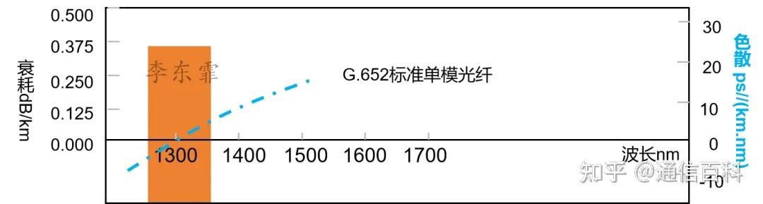
Above we mentioned several key parameters of the O-band, such as Rayleigh scattering loss, OH absorption loss, bending loss, and dispersion.
Some friends may be confused. In specific applications, should we look at attenuation or dispersion?
In terms of attenuation, the O-band is overall a bit higher than the C-band, but it wins in low dispersion. Therefore, the O-band is often used in scenarios less sensitive to loss, such as data center interconnects within 2 km, 5G fronthaul of about tens of kilometers, and the G.657 fiber FTTH scenarios mentioned above.
If the distance is farther, such as 40 km, 80 km, or even 100 km, then attenuation becomes more important, and it may be necessary to pair with an SOA amplifier.
For multimode fiber systems, the O-band (mainly referring to the 1310 nm window) is also often used, usually paired with a multimode light source (such as a VCSEL). There are also multimode fibers with single-mode light sources, but they are less common.
The main application scenarios of the O-band include data center interconnection, 5G fronthaul, PON access, and so on. In these scenarios, the lasing wavelengths of lasers vary, but they are all based on CWDM coarse wavelength division multiplexing technology. Standard CWDM has 18 wavelengths, but only 5 wavelengths truly fall in the O-band, with a spacing of 20 nm between each wavelength.

But in data centers, the first four wavelengths are used more, abbreviated CWDM4, namely the 1271 nm, 1291 nm, 1311 nm, and 1331 nm wavelengths. These wavelengths are all within the O-band, with not-too-large attenuation, but the dispersion is truly low.
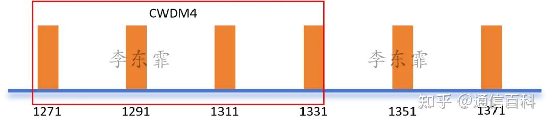
The larger 20 nm wavelength spacing reduces the requirements on laser wavelength accuracy and temperature control, so a lower-cost DML (directly modulated laser) can usually be used, thereby significantly reducing the cost of the entire optical module.
Similar to it is LWDM4, which is also within the O-band range. The center wavelength spacing of the four channels is about 4.5 nm (800 GHz), namely 1295.56 nm, 1300.05 nm, 1304.58 nm, and 1309.14 nm. It is mainly designed for 10 km transmission (covering broader data center campus or access network edge requirements).
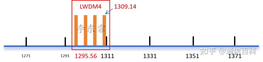
Because LWDM4 has a narrow wavelength spacing (4.5 nm), it requires more precise wavelength control and stricter temperature control. A DFB with better wavelength stability is usually used. This leads to a relatively higher module cost. Therefore, if CWDM4 can solve the problem, the LWDM4 scheme is generally not chosen.
Among the CWDM6 wavelengths of 1271 nm, 1291 nm, 1311 nm, 1331 nm, 1351 nm, and 1371 nm, the first five are within the O-band, with a wavelength spacing of 20 nm, while 1371 nm is in the E-band. Application scenarios include intra-data-center interconnection, 5G fronthaul/midhaul, and enterprise network core links, etc.
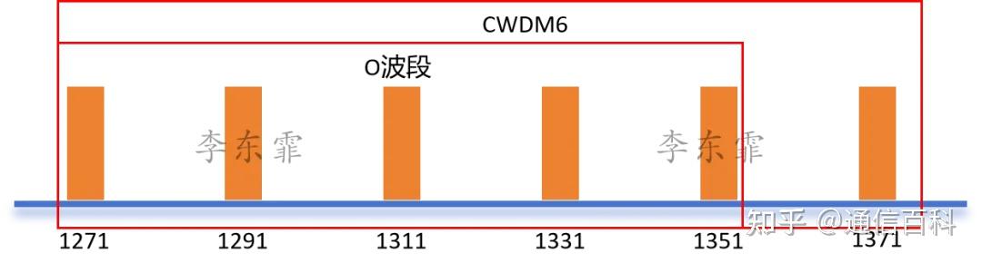
However, it should be noted that the 1351 nm wavelength is close to the edge of the water peak, and its loss in standard fiber is slightly higher than that of 1331 nm.
In the 25G BiDi (bidirectional) scheme of 5G fronthaul, the 1270 nm and 1330 nm wavelengths in the O-band are usually used for uplink and downlink transmission.
In addition, in the PON field, the O-band is also very widely used.
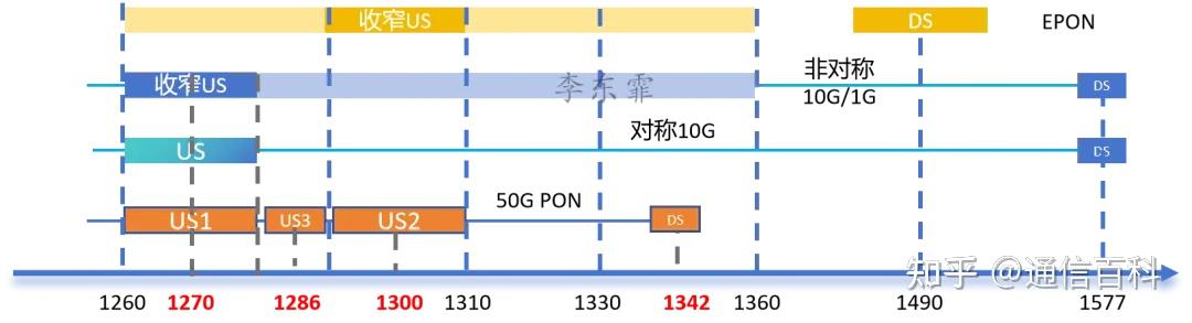
For example, the uplink of EPON/GPON uses the 1310 nm wavelength, which belongs to the O-band, while the downlink uses the 1490 nm wavelength. The 10G-EPON uplink band, such as XGPON, uses the 1270 nm wavelength for uplink.
The uplink transmission of 25G PON can use wavelengths such as 1270 nm, 1286 nm, or 1300 nm. This design is mainly to achieve wavelength coexistence with existing GPON, XG(S)-PON and other systems on the same optical distribution network (ODN).
50G PON uses 1270 nm/1286 nm/1300 nm/1310 nm as uplink wavelengths, and 1342 nm for downlink, all belonging to the O-band. It is understood that the domestic industry has basically converged on choosing 1286 nm for the 50G PON uplink wavelength.
We supply various data-rate AOC/DAC/MPO cables, optical modules, and transceivers, along with optical components used within them, such as aspheric lenses, collimating lenses, aspheric lens arrays, waveplates, etc. Custom development services are also available.
Contact us via Email: market@bitwavx.com
Enjoy this article?
Subscribe to get new optical communication insights delivered to your inbox. Free, unsubscribe anytime.