Extinction Ratio, abbreviated as ER.
It is determined by the optical power P1 of logic “1” and the optical power P0 of logic “0”. The larger the ratio between the two, the higher the extinction ratio.

In an eye diagram, the extinction ratio directly reflects the degree of separation between the “1” level and the “0” level. The larger the extinction ratio, the more fully the eye opens, the clearer the level distinction, and the stronger the signal’s noise immunity.
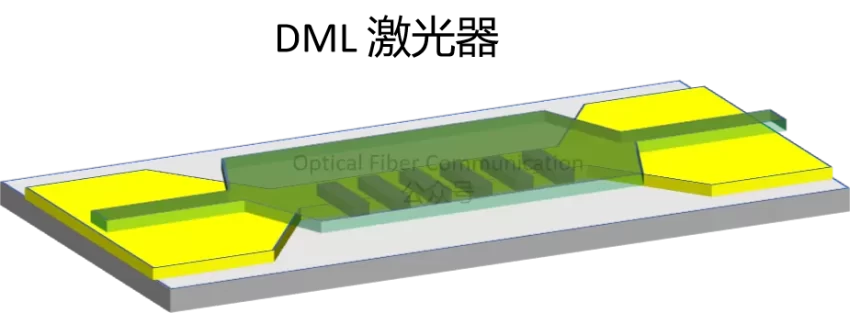
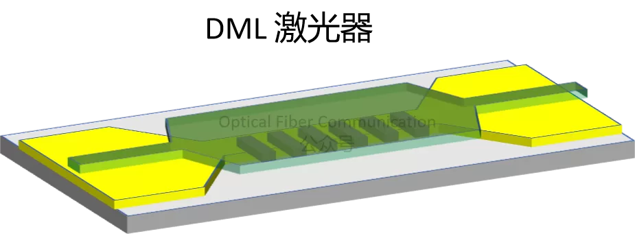
A DML laser has only one active region and must accomplish both light emission and modulation simultaneously, using direct modulation.
Nokia: TFLN Two-Electrode Modulator Solution Supporting Single-Ended/Differential Driving
When the injected current exceeds the threshold, it produces stimulated-emission optical output power; the power difference formed by the two operating levels constitutes the DML’s extinction ratio.
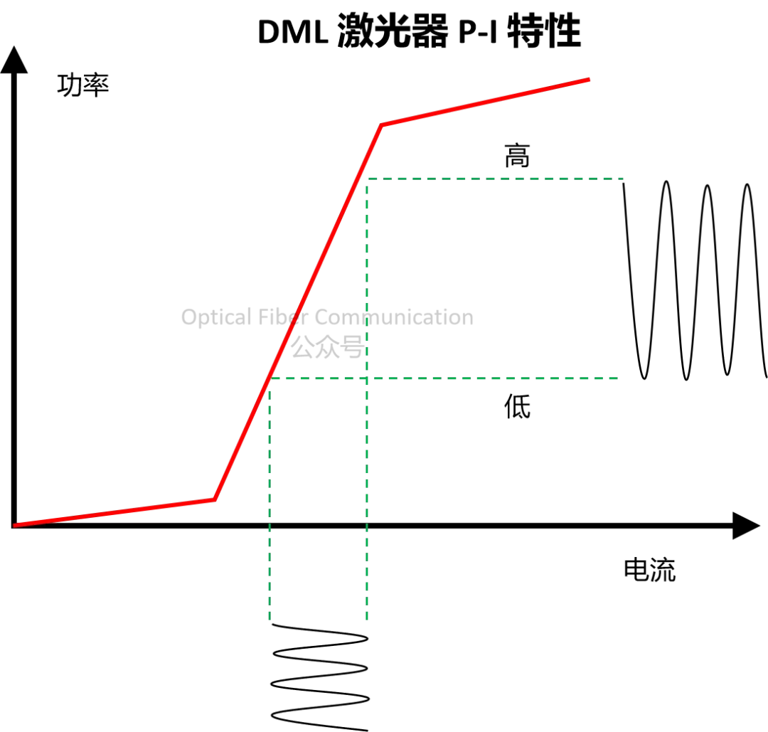
But even if the “0”-state current is pushed below the threshold, there is still spontaneous-emission floor power, and P0 cannot reach zero, so the DML’s extinction ratio is generally not high.
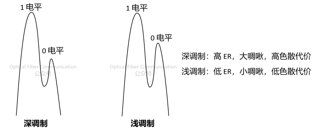
The DML relies on current magnitude variation to achieve modulation, which also changes the active region’s refractive index. If deep modulation is used to force a higher extinction ratio, it will produce chirp and introduce dispersion penalty, limiting high-speed long-distance transmission.
Unlike the DML, the EML structurally splits light emission and modulation into two independent parts: the front is a DFB laser, and the rear is an EA electro-absorption modulator.
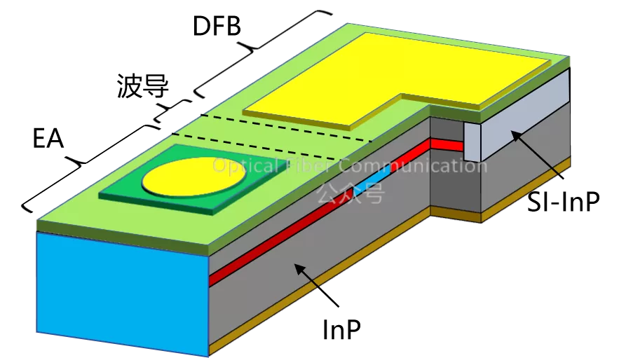
Source Photonics: High-Speed EML Chip Process Flow and Improvements
The EA modulator is only responsible for controlling the on/off of light. When outputting logic “0”, it absorbs the optical signal heavily, causing the transmittance to drop sharply, so P0 can be pushed to an extremely low level, without the spontaneous-emission floor limitation of the DML.
Generally, we can obtain the desired ER by adjusting the reverse bias voltage.
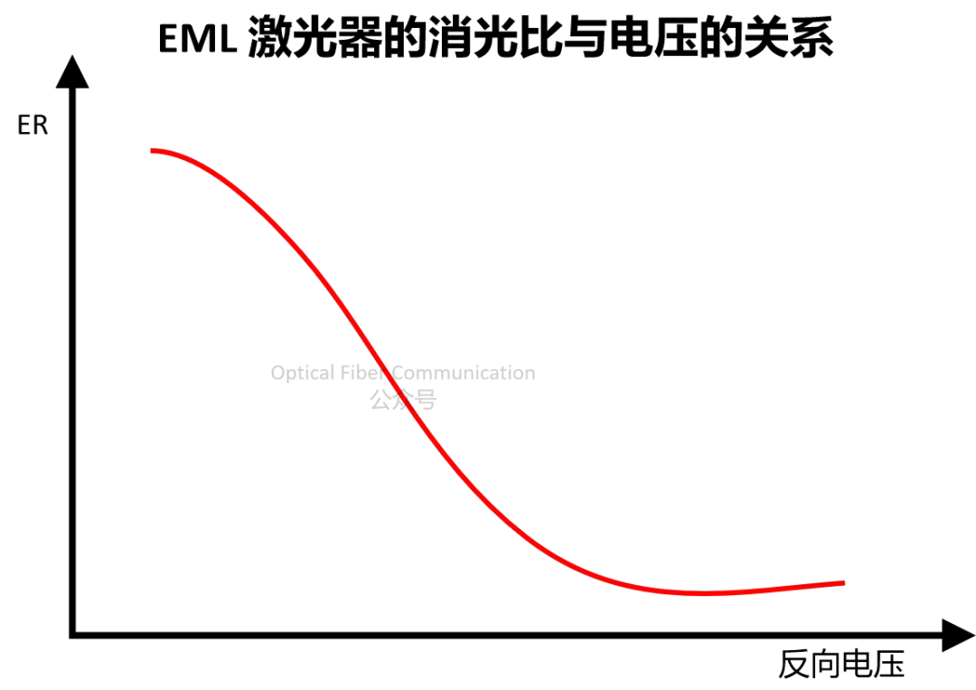
The DFB laser of the EML operates at constant current with stable emission and does not participate in switching modulation, so the carriers and refractive index are constant, eliminating chirp at the root. At the same time, the EA modulator only adjusts light intensity through reverse voltage without changing the wavelength, so there is no additional chirp.
Therefore, the EML’s extinction ratio can be made very high. And a high extinction ratio allows better receiving sensitivity at the receive end.
But for the transmit end, ER is not the higher the better – or rather, moderate to low is more favorable. An excessively high ER requires greatly suppressing the “0” level and increasing the modulation amplitude, which increases the burden on the device and driver and causes problems such as waveform distortion and increased chirp.
If the modulator length is extended to improve ER, the device capacitance increases, and the modulation bandwidth will be limited by the RC time constant.
Thanks for reading!
Related articles:
Source Photonics: 400G/lane EML Solution and 3.2T Optical Module Roadmap and Views
High-Speed EML Laser Anti-Reflection Structures and Solutions
224Gbps Single-Ended Drive EML COC Package Solution
Related Reading
- Why Does an EML Transmit Farther Than a DFB?
- Coherent: Traveling-Wave Electrode High-Speed EML Solution
- What Is an EML? Working Principle, Applications, and Evolution of Electro-absorption Modulated Lasers
Enjoy this article?
Subscribe to get new optical communication insights delivered to your inbox. Free, unsubscribe anytime.