Alibaba Cloud: Progress and roadmap of 3.2T NPO technology
Tencent: Progress and large-scale deployment of 3.2T NPO near-packaged solutions
STMicroelectronics: Progress of the silicon photonics process platform supporting NPO/CPO
Eoptolink: NPO optical engine based on VCSEL
Recently I have written quite a few articles on NPO, so today let me briefly sort out the knowledge of NPO.
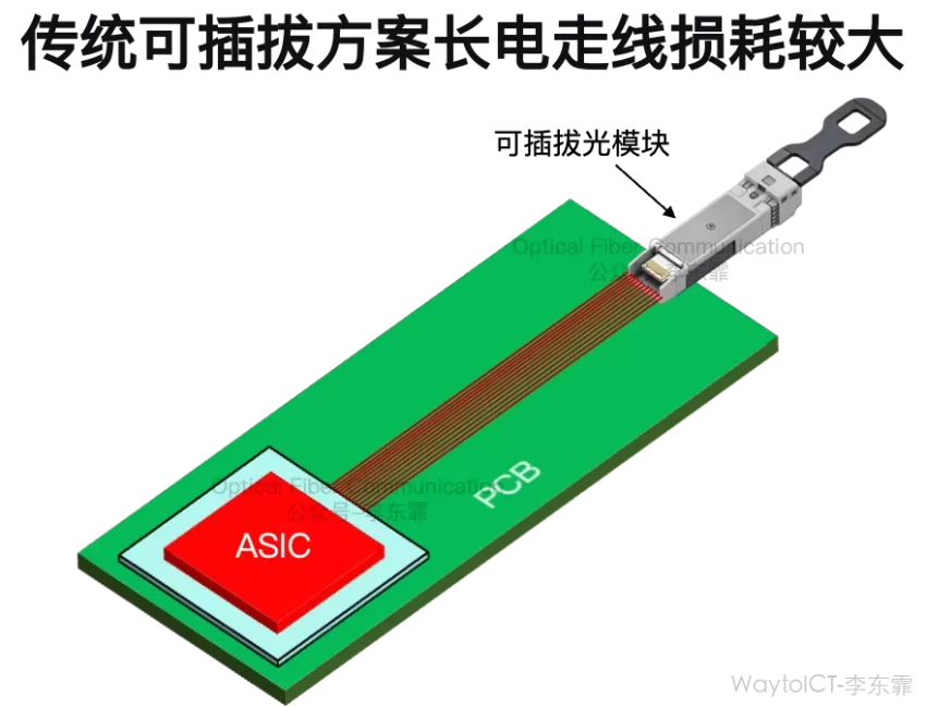
In data centers, power consumption and heat dissipation are among the biggest costs. Traditional pluggable optical modules must carry electrical signals over a dozen to several dozen centimeters, and the I/O interface power consumption is very high.
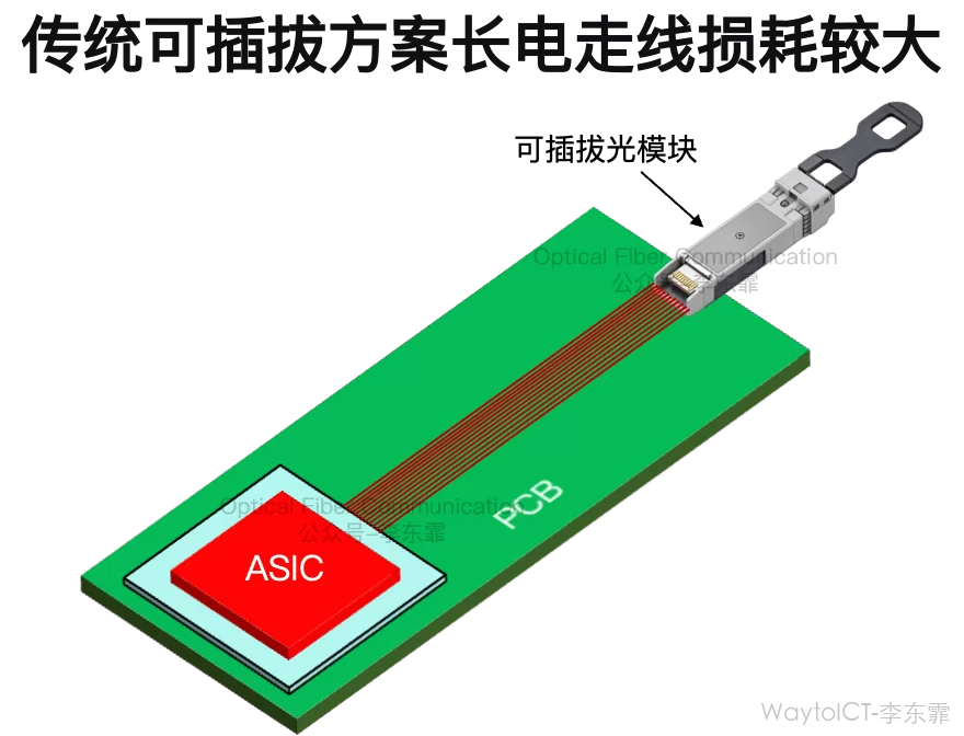
Such long-distance routing causes severe insertion loss and signal distortion. To compensate, the system has to use high-power Retimer chips and expensive ultra-low-loss PCB materials.
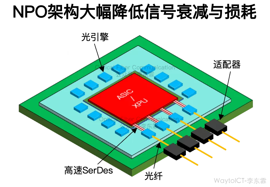
So, the purpose of NPO is to move the optical engine from the panel edge to beside the ASIC chip (near-packaged). The electrical signal only needs to travel a few centimeters or even a few millimeters on the PCB to reach the optical engine.
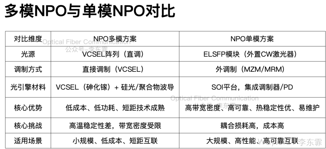
The NPO system architecture can be divided into two categories by light-source origin: the NPO multimode solution and the NPO single-mode solution.
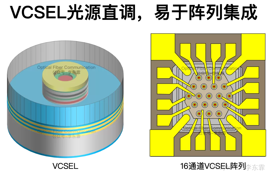
In the NPO multimode solution, the light source is a VCSEL array, directly integrated inside the NPO optical engine. After the optical engine uses the VCSEL array to generate modulated light, it couples it to the output interface of the NPO module through a fiber array.
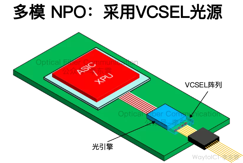
VCSEL is a directly modulated light source; changing the injection current can directly modulate a high-speed optical signal without a separate silicon photonic modulator. The structure is simple and low-cost, but the transmission distance is short.
The NPO single-mode solution uses an external laser source (ELS), that is, the laser is separately packaged into an ELSFP module conforming to the OIF standard definition, and this module provides continuous-wave light to the NPO optical engine.
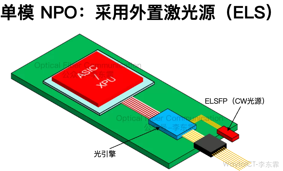
The light source provided by the ELSFP is input into the NPO optical engine through a polarization-maintaining fiber array. The ELSFP and the OE are usually connected through MPO/MT connectors.
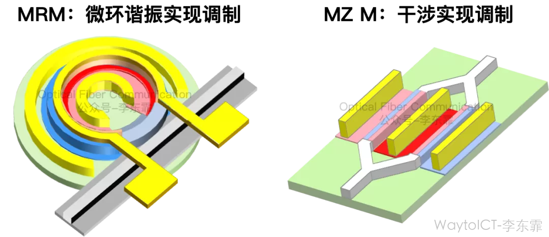
The optical engine internally integrates a silicon photonic MZM modulator or a microring MRM modulator to modulate the electrical signal onto the CW light.
The advantage of using an external CW light source is that the ELSFP and the optical engine are physically separated, so the laser heat does not affect temperature-sensitive optical engines, such as those based on microring modulators.
At the same time, the ELSFP supports front-panel hot-swapping; if the laser fails, only the ELSFP module needs to be replaced, without disassembling the entire NPO module.
Whether single-mode or multimode NPO, the industry recommends reusing existing mature standard gold-finger connector cages such as QSFP-DD/OSFP-XD/OSFP, packaging the NPO optical engine in the form of a traditional pluggable optical module.
Based on the standardized gold-finger standards, the connection layout between the NPO module and the PCB mainboard mainly has two types: horizontal and vertical.
In the horizontal layout, the NPO module is parallel to the mainboard, laid flat around the main chip through gold fingers. The process is mature, but it occupies a large planar area.
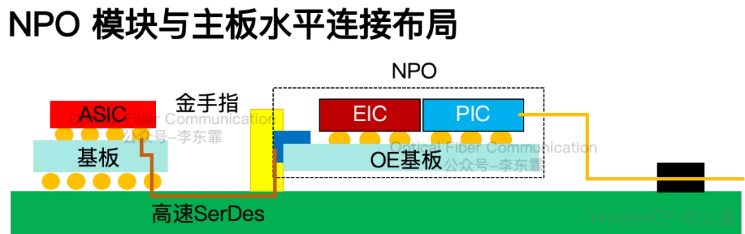
The double-layer connector form already maturely applied in pluggable optical modules can be adopted; through double-layer stacking, the number of optical channels can be doubled without increasing the module width.
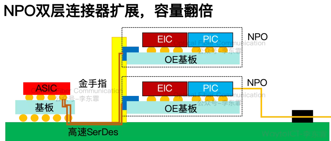
The other is that the NPO module is perpendicular to the mainboard, plugged upright through vertical gold fingers, saving the planar space around the main chip, but with requirements on vertical height.
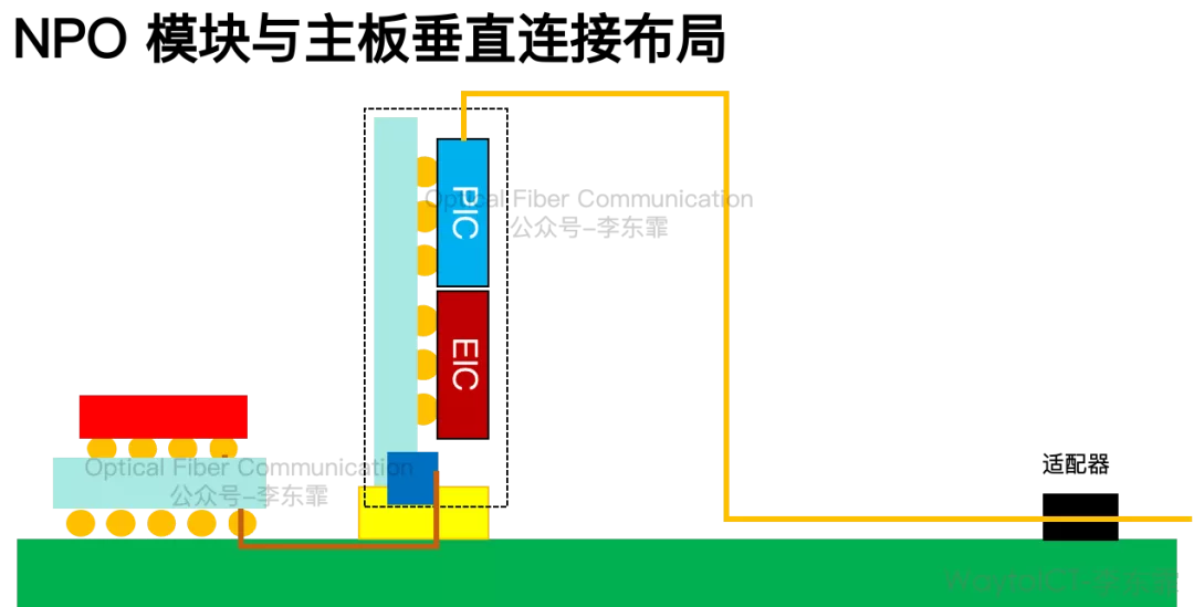
Reusing existing mature MSA industry standards such as QSFP-DD/OSFP-XD/OSFP eliminates the need to develop a brand-new interface standard and can directly connect to existing switch ASICs.
Finally, let me briefly summarize and compare.
Two Types of CPX Socket Interfaces Supporting NPO and CPO
Murata: NPO/CPO Technology and Evolution Roadmap Based on Low-Temperature Co-fired Ceramics
Marvell: Views on Optical Interconnect Selection and NPO Opportunities and Challenges for AI Clusters
Thank you for reading,
and please forgive any inaccuracies!
The optical chip, optical device, and optical module (OFC2026) report compilation, color-printed and A4-bound, in two volumes totaling about 525 pages and about 200,000 characters. If you need it, welcome to contact us to order; the price is affordable!
Related Reading
- NPO Basics: Multimode and Single-Mode Solutions and Packaging Layout (Video Version)
- How Did the Packaging and Multiplexing Path from OTN to Flexible FlexO Evolve?
- What Packaging Processes Are There for Optical Modules?
Enjoy this article?
Subscribe to get new optical communication insights delivered to your inbox. Free, unsubscribe anytime.