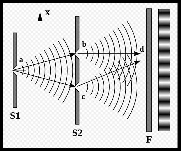
The moment I understood the principle of the Mach-Zehnder (M-Z) modulator, I thought of the double-slit experiment, which I believe we are all familiar with.
It was first performed by Thomas Young in 1801 to demonstrate the wave nature of light. In this experiment, a beam of light passes through two very close slits and then forms a series of alternating bright and dark fringes on an observation screen. These fringes are formed by the interference of the light waves emitted from the two slits. Bright fringes appear where the light waves interfere constructively, while dark fringes are the result of destructive interference.
The Mach-Zehnder (M-Z) modulator we are going to discuss today is essentially based on the same principle. The first question is how to create two light beams of the same frequency, while also allowing us to control the phase difference between them to produce interference at the output. To this end, let us first look at the M-Z interferometer, which is the foundation, and then discuss the M-Z modulator. How is the M-Z interferometer implemented? Look at the illustration below.
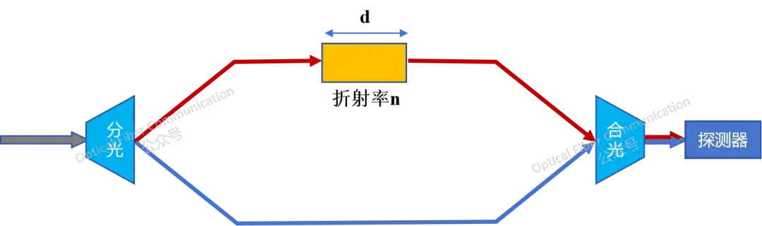
In the figure above, a beam of coherent light is split into two beams at the beam splitter. One beam goes directly to the combining point, while the other passes through a medium with refractive index n and length d. In this way, the two artificially split beams are given different optical path differences Δd. This optical path difference can be calculated. Assuming the two split beams have the same path length, the optical path difference is mainly caused by the medium in between.
Δd = nd
The resulting phase difference is our goal:
Δφ = (2π/λ) * Δd = (2π/λ) nd
We adjust the refractive index n and length d. When the phase difference is exactly π, that is, Δφ = π, the two same-frequency beams interfere destructively at the combining point, and the light received by the detector is 0; when the optical path difference Δφ = 0 or a multiple of 2π, the two beams interfere constructively, and the light intensity received by the detector is at its maximum.
The above is the principle of the M-Z interferometer.
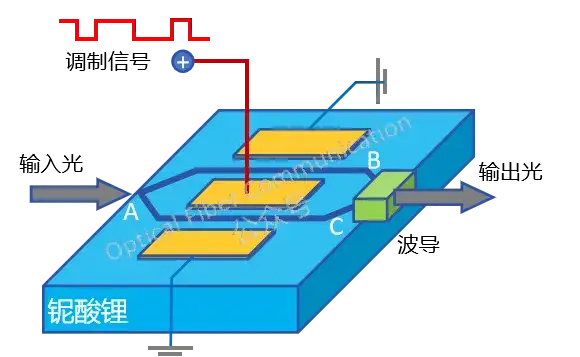
In the M-Z modulator, the input light is also split into two equal signals. The difference is that the two beams respectively enter the two optical arms of the modulator, and these two arms use electro-optic materials, whose refractive index changes with the magnitude of the externally applied electrical signal.
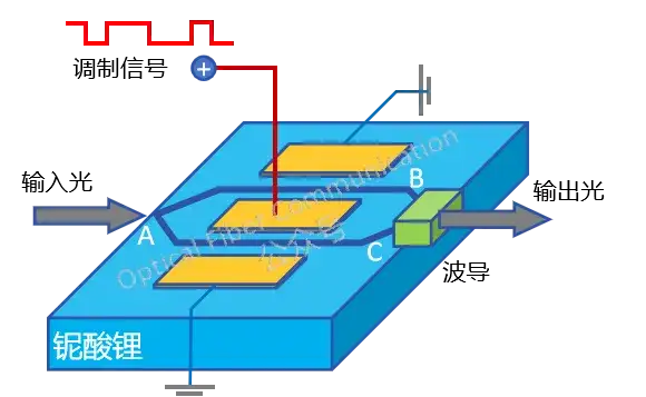
As shown in the figure above, let us look in detail. The input light is equally divided at point A into the two optical arms B and C for transmission. We apply opposite electric fields to the two arms, controlled by the modulation signal, so the refractive-index changes in the two arms are opposite, and thus the phase difference Δφ caused by the optical path difference Δd is also opposite.
If a phase difference of π/2 is introduced in arm B and a phase difference of -π/2 in arm C, the two beams together undergo a total phase change of π at the combining point.
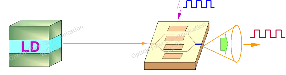
In this way, we can adjust the phase difference through the loaded modulation signal, converting the electrical signal information onto the optical signal. The optical signal synthesized at the output becomes an interference signal whose intensity varies with the modulation voltage, achieving optical intensity modulation.
Thank you for reading!
Published with the permission of the OFC official account; for more knowledge, you can follow its account:

Related Reading
- What Is the Use of the Carrier Effect in Silicon Photonic Modulators?
- Ge Electro-Absorption Modulator
- NVIDIA: Design Approach for a High-Speed Microring Modulator Beyond 200G per Lane
Enjoy this article?
Subscribe to get new optical communication insights delivered to your inbox. Free, unsubscribe anytime.