
A fan sent us a private message in our community: “Why is the fiber end face usually polished at an 8-degree angle?” I believe everyone is already very familiar with the structure and transmission principle of fiber, so let us go straight to two images:
The figure below is a fiber with a vertical end face. A portion of the light is reflected back into the core at a certain angle, and the reflected light may interfere with the original signal, causing signal quality degradation, and in severe cases may even damage the laser source.

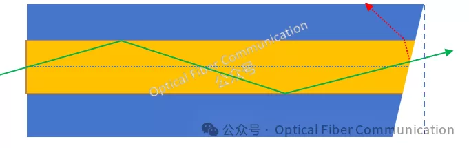
The figure below is an end face polished into an 8-degree bevel. The light reflected from the end face is guided into the cladding, thereby preventing the reflected light from returning to the fiber core, which helps improve return loss and lets more light transmit through the fiber.
This involves the concept of return loss:

Taking the common fiber core refractive index n1=1.45 @1550nm as an example, with the refractive index of air n2 = 1, substituting into the formula: return loss about -14.77 dB, where the reflectivity:

We can get R about 0.03366, meaning about 3.37% of the light is reflected back. So we need to think of some solutions! For example, grinding and polishing the fiber end face so that the end faces of the two fibers can make better contact. Usually, to achieve better contact, a spring is also used to press the connector end face, optimizing the performance of the fiber connector. Based on this, there are the following three types of physical-contact end faces:
- PC (Physical Contact), physical contact
- UPC (Ultra Physical Contact), ultra physical contact
- APC (Angled Physical Contact), angled physical contact
Among them:
Physical contact (PC): the mating end face has a convex dome structure, with a flat connector cross-section, and the ferrule surface is ground into a slight spherical shape.

Ultra physical contact (UPC): optimized on the basis of PC, with a slight curvature on the connector end face, making the mating between fibers more precise.

Angled physical contact (APC): the fiber end face is usually ground into an 8-degree bevel, and the 8-degree bevel makes the fiber end face tighter.

The return loss of APC is the best among the three types of contact faces. In general, the return loss of fiber patch cords using PC polishing is -40dB. The return loss of UPC is higher than that of PC, generally -55dB. The industry-standard return loss of APC is -60dB. The three so-called physical contacts above mean that they must be pressed tightly together. The physical contact here is also to distinguish from the later non-physical contact.
In recent years, many optical modules have adopted the new “non-physical contact” technology. So why is it an 8-degree angle, not 6 degrees or 9 degrees? Here we need to recall the definition of numerical aperture again: not all light incident on the fiber end face can be transmitted by the fiber; only incident light within a certain angle range can be transmitted.

The sine of this angle alpha is called the numerical aperture of the fiber. NA = sin(alpha). The numerical aperture (NA) of G.652 single-mode fiber is usually between 0.125 and 0.145. Taking 0.13 to calculate alpha: alpha = 7.6 degrees. That is, when the end face is greater than 7.6 degrees, the light reflected from the fiber end face enters the cladding. In practice, considering various factors such as insertion loss and equipment precision, it is made into 8 degrees. Actually 9 degrees or 10 degrees would also work, but they would increase insertion loss, which is not worthwhile.

Thanks for reading!
Published with authorization from the OFC official account.
You can follow the OFC official account:

Related Reading
- What Is the Propagation Path of Light in Optical Fiber?
- Optical Fiber Communication: The Structure of Optical Fiber
- Optical Fiber Communication: Mode Field Diameter and Cutoff Wavelength
Enjoy this article?
Subscribe to get new optical communication insights delivered to your inbox. Free, unsubscribe anytime.