In an article a few days ago, we roughly sorted out the differences between concepts such as “Silicon Photonics, Optical Engines, Optical Modules and CPO“.
Today, let’s continue to look at the differences among pluggable optical modules, on-board optics (OBO), NPO, and CPO.
The development of optical modules has always pursued higher density, lower power consumption, and stronger performance. The earliest pluggable standard was GBIC in 1995, while the one that truly became popular was SFP, which emerged around 2000.
1.6T/3.2T Optical Modules: Half-DSP, Half-LPO Hybrid Architecture
Google/Coherent and Others: Pluggable vs. CPO vs. OCS
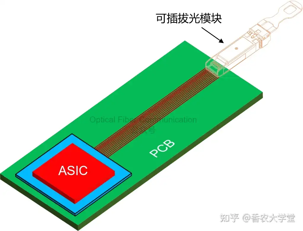
Since then, technology has iterated rapidly. Since 2015, the mainstream trend has shifted toward more compact, high-density designs such as QSFP56, QSFP-DD, and OSFP.
These modules are usually installed at the edge of the PCB, while the core chip for data processing, the ASIC, is located on a separate package substrate. The core advantage of pluggable modules lies in their flexibility and easy replacement.
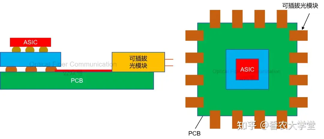
But this layout has a clear shortcoming: the photoelectric conversion chips (PIC/EIC) inside the optical module are farthest from the ASIC, and electrical signals must travel through long PCB traces, increasing power consumption and affecting signal integrity.
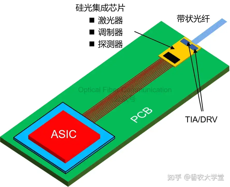
To reduce the signal loss caused by long PCB traces, the industry began exploring the “on-board optics” (OBO) solution around 2018.
The idea is to take the optical engine and electrical engine (PIC/EIC) out of the module and mount them directly on the same PCB where the ASIC is located, usually arranged around the ASIC.
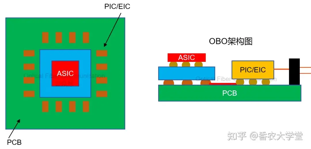
The idea is to take the core of the optical transceiver, namely the optical engine and electrical engine (that is, PIC/EIC), out of the pluggable module and place them directly on the same PCB as the packaged ASIC chip, usually around the ASIC.
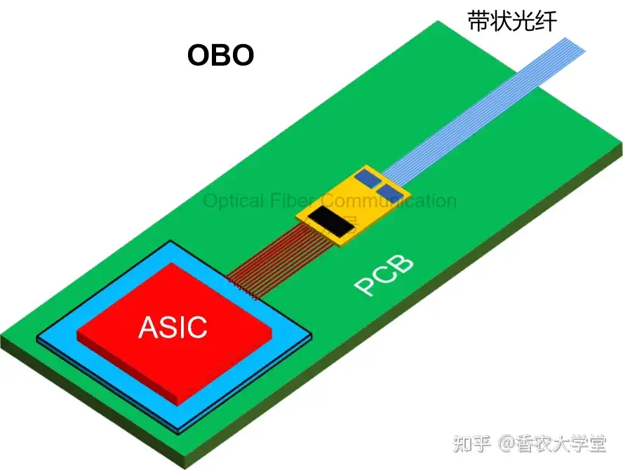
In this way, the connection between PIC/EIC and ASIC is completed through traces inside the PCB, greatly shortening the distance, so power consumption and signal quality are naturally improved.
Starting around 2020, the more advanced “near-package optics” (NPO) began to emerge.
Broadcom & HiSilicon: VCSEL NPO/CPO and Silicon Photonics CPO
The NPO design is more aggressive: it places the optical engine/electrical engine on a dedicated optical sub-substrate, then places this optical sub-substrate side by side with the packaged ASIC, integrating them on the same high-performance package substrate.
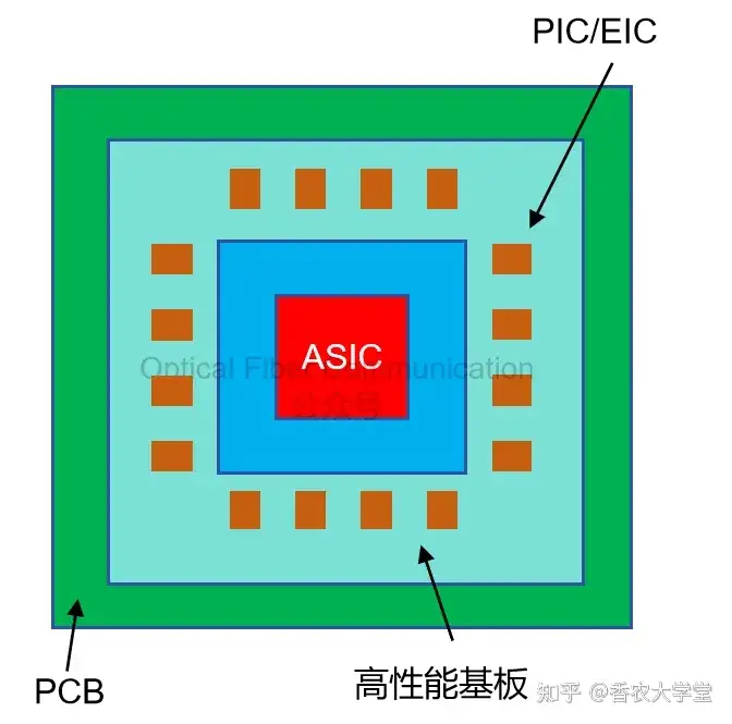
Its key improvement is that high-speed signals no longer need to pass through the main board PCB, but are connected through this higher-performance package substrate, so the loss is smaller and the electrical performance is better.
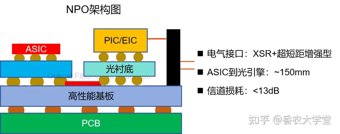
According to the OIF definition, in the NPO architecture the distance from ASIC to optical engine can reach 150mm, and the channel loss needs to be controlled within 13 dB. To this end, OIF is promoting the “extra short reach enhanced” (XSR+) electrical interface standard.
Next, let’s look at CPO. Its concept was proposed earlier than NPO, but it was not until around 2023, with Intel, Broadcom and other companies beginning to ship, that CPO attracted widespread attention.

Articles related to CPO:
Cisco: Pluggable CPO Optical Interface Solution
e-Tube Plastic Waveguide Solution Supporting CPO
Glass Substrates: Pluggable Connection Solutions in CPO Packaging
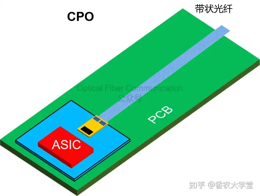
CPO can be regarded as one of the ultimate forms of optoelectronic integration: it integrates the optical engine/electrical engine side by side with the ASIC directly around the same co-packaged substrate. This minimizes the distance between the ASIC and PIC/EIC, theoretically achieving the best electrical performance.
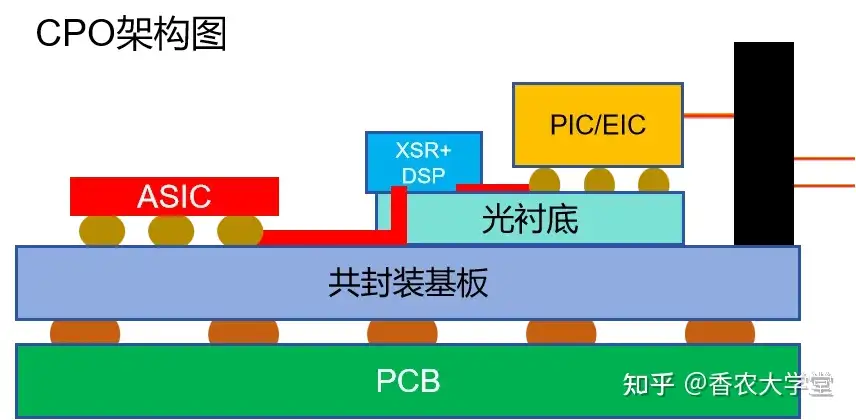
In short, NPO moves the optoelectronic devices to the side of the ASIC package substrate, while CPO seals both into the “same room”, thus having advantages in size, power consumption, and latency.
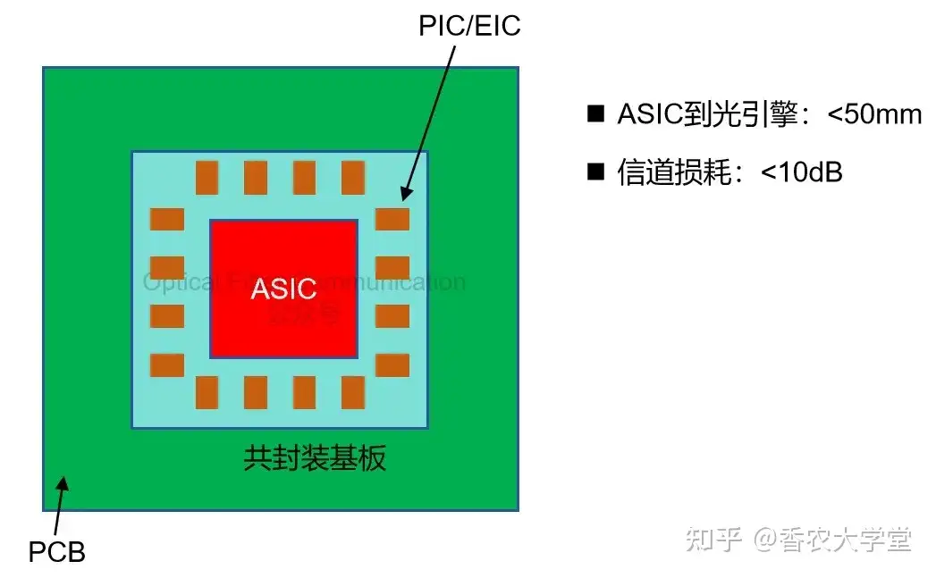
The goal OIF sets for CPO is: the distance between the optical engine and ASIC is less than 50mm, and the channel loss does not exceed 10 dB.
The shorter interconnect distance and the loss savings of about 3 dB enable CPO to potentially achieve lower system power consumption.
Thanks for reading!
Related Reading
- Scale Up: Is It PLO, NPO, or CPO?
- Murata: NPO/CPO Technology and Evolution Roadmap Based on Low-Temperature Co-fired Ceramic
- Two Types of CPX Socket Interfaces Supporting NPO and CPO
Enjoy this article?
Subscribe to get new optical communication insights delivered to your inbox. Free, unsubscribe anytime.