The day before yesterday I wrote about Mitsubishi’s glass-substrate dual-EAM differential EML flip-chip scheme at ECOC 2026.
Whether at OFC 2026 or ECOC 2026, its EMLs all adopt a dual-EAM series structure.
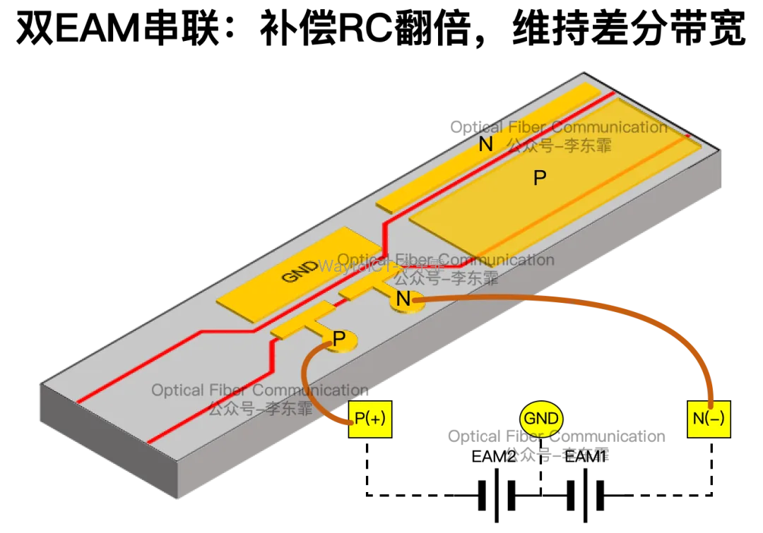
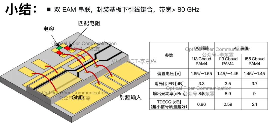
The anode of EAM1 and the cathode of EAM2 are tied to a common ground, the two EAMs have exactly the same physical length, and an SSC spot-size converter is used to improve fiber coupling efficiency.
By connecting the two EAMs in series, the total capacitance is halved, which exactly offsets the doubling of the RC time constant caused by the 100-ohm termination resistor under differential drive.
Meanwhile, electrical isolation is provided between the DFB and the two EAMs, so the differential drive voltage is applied only to the EAM electrodes, preventing signal leakage into the laser and crosstalk between the two EAMs.
For differential RF high-speed signals, termination schemes are mainly divided into two types: DC termination and AC coupling.
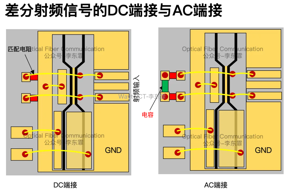
The core difference between the two schemes lies in how the termination matching resistor is grounded. Because the EAM requires a DC bias voltage to operate, this involves the path of the DC current.
In DC termination, the 50-ohm termination resistor is connected directly to the ground plane of the substrate, so the DC current generated by the bias flows directly through the resistor to ground.
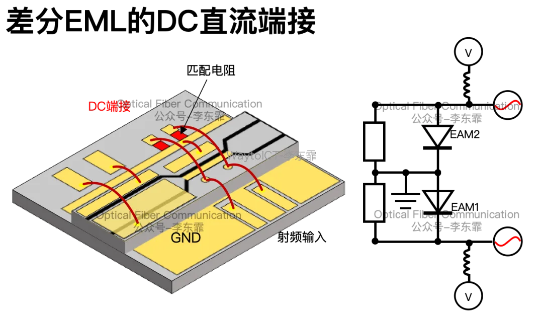
Current flowing through the resistor generates heat and consumes power, and data centers have extremely high requirements for low power consumption.
But DC termination resistors are grounded independently, so the photocurrents of the two EAMs can be drained separately, providing high tolerance to process imbalance and current mismatch, and the low-frequency common-mode response does not degrade.
At OFC 2026 in the first half of the year, Mitsubishi used chip-on-carrier (CoC) wire bonding and measured a 3-dB bandwidth exceeding 100 GHz at the limit.
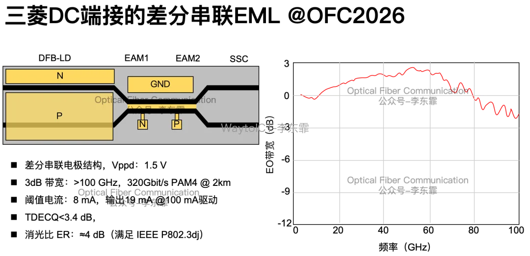
The threshold current was 8 mA, and at a DFB-LD injection current of 100 mA, the output power reached 19 mW.
At ECOC 2026, Mitsubishi switched to sub-mount packaging. Under DC termination, 113 GBaud PAM4 testing achieved a TDECQ of 0.96 dB, and the 3-dB electro-optic bandwidth reached 80 GHz.
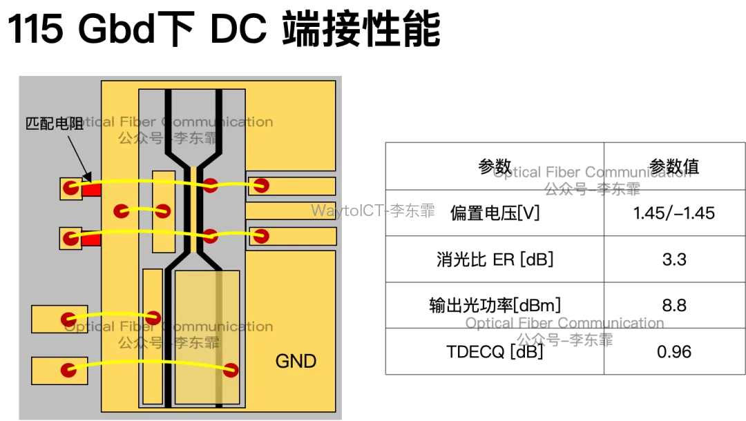
At this point the EAM bias voltage was +1.65 V / -1.65 V, the extinction ratio was 3.3 dB, and the output power was 8.8 dBm. The difference between differential and common mode was greater than 10 dB, with good low-frequency common-mode rejection.
To solve the high power consumption caused by DC bias current flowing through the resistor, Mitsubishi introduced an AC coupling scheme, i.e., a DC-blocking capacitor in series between the resistor and ground.
To save packaging area, Mitsubishi did not give each of the two 50-ohm resistors its own capacitor; instead it connected the two resistors together and shared a single 10 nF AC coupling capacitor to ground.
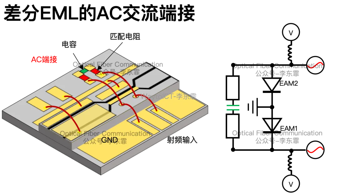
The DC-blocking capacitor blocks DC and lets only the high-frequency RF signal reach ground. This achieves RF matching while blocking DC current, greatly reducing power consumption.
Measured at 113 GBaud PAM4, the 3-dB bandwidth with AC termination remained at 80 GHz.
At this point the AC termination positive/negative bias was +1.45 V / -1.45 V, TDECQ was 0.59 dB, extinction ratio 3.5 dB, and output power 8.9 dBm.
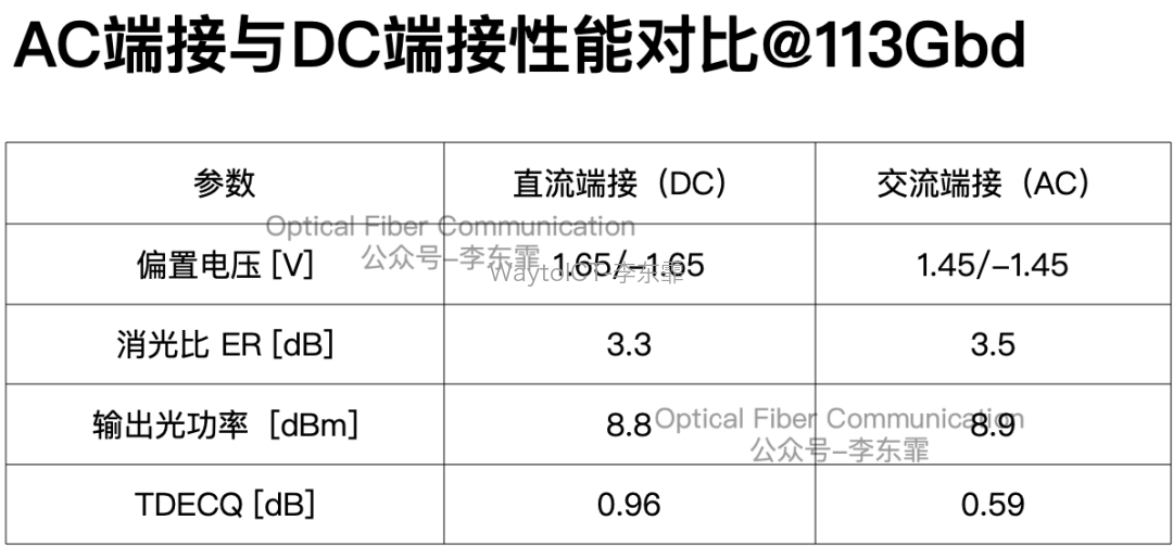
It can be considered that at 113 GBaud, the modulation performance of AC termination and DC termination is almost identical.
Mitsubishi achieved 360 Gb/s with DC termination at OFC 2026, but it consumed too much power.
Therefore, Mitsubishi ran a 155 GBaud (310 Gb/s) test based on AC termination. At 100 mA current and 1.2 Vppd swing, it achieved a TDECQ of 2.1 dB, extinction ratio of 3.7 dB, and output power of 9.0 dBm.
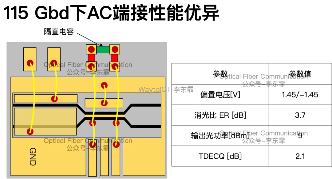
Of course, the single-capacitor AC scheme also has risks. If the dual-EAM photocurrents are unbalanced and lack independent grounding, the common-mode response may degrade, whereas DC termination has no such risk.
In the article a few days ago, I also discussed Mitsubishi’s glass-substrate flip-chip scheme, which likewise uses AC coupling. Flip-chip is used to reduce the per-channel area and improve integration density.
But this sacrifices performance: the bandwidth dropped from 80 GHz with wire bonding to 60.3 GHz.
Finally, a brief summary.
Thanks for reading, and apologies for any inaccuracies!
Further reading:
Innolight: EML MPD-free optical power monitoring based on EAM photocurrent
Coherent: traveling-wave electrode high-speed EML scheme
Lumentum: 4x200G differential-drive EML progress
The OFC 2026 report compilation on optical chips, optical devices, and optical modules is printed in color with A4 binding, two volumes totaling 1000+ pages, about 1700 hand-drawn structure diagrams and about 200,000 words. Contact us to order at an affordable price!
You can add WeChat WaytoICT to join the Semiconductor & Optical Device Industry Group 2.
Welcome to join our community for high-value technical documents, trend reports, and supply-demand opportunities in the semiconductor chip, optical device, and optical module fields.
If you are interested in semiconductors, optical devices, optical modules, and fiber-optic communications, welcome to follow us!
Related Reading
- Maximum coupling loss (MCL) and maximum path loss (MPL)
- How to couple VCSEL light into the PIC wafer plane?
- Silicon photonics series 2: what is a grating coupler?
Enjoy this article?
Subscribe to get new optical communication insights delivered to your inbox. Free, unsubscribe anytime.