In high-speed optical modules at 100G/200G/400G/800G and up to 1.6T/3.2T/6.4T, the EML (Electro-absorption Modulated Laser) is an almost indispensable core light source. It monolithically integrates a DFB laser and an electro-absorption modulator (EAM) on the same InP substrate, retaining the narrow linewidth and high power of the DFB while leveraging the high-speed electro-absorption effect of the EAM for NRZ/PAM4 modulation. For LR/ER scenarios below 10 km, the EML has become the “standard answer” for 200G/lane and above.
1. What Is an EML? Basic Structure
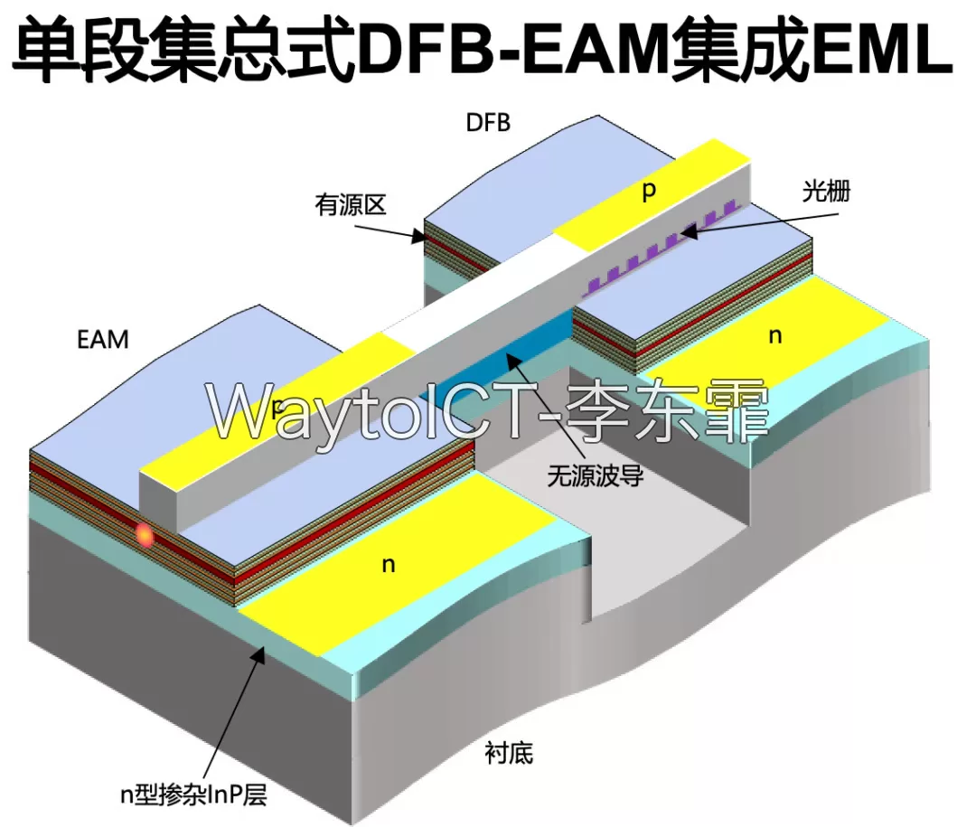
An EML consists of two active sections:
- DFB section (Distributed Feedback Laser): provides a stable continuous-wave (CW) light source, with the lasing wavelength determined by the Bragg grating period.
- EAM section (Electro-Absorption Modulator): a passive waveguide; when reverse bias is applied, its band-edge absorption shifts toward longer wavelengths (via the Franz-Keldysh effect and the quantum-confined Stark effect), thereby modulating the transmitted optical intensity.
The DFB and EAM are connected by a passive waveguide (see the figure below), operating near 1310 nm (O-band), suitable for CWDM4, LR4, FR4, and DR4 interconnect scenarios at 2 km / 10 km reach.
2. Working Principle of the EML
The modulation principle of the EML is based on the electro-absorption effect: as the reverse bias on the EAM changes, the material’s absorption edge shifts accordingly. Light originally passing through the EAM is partially absorbed, and the output intensity varies with bias voltage — this is the physical basis of NRZ modulation.
PAM4 modulation uses four different bias levels (corresponding to the four symbols 00/01/10/11) to achieve 2 bits/symbol transmission, enabling rates above 100G/lane when combined with DSP.
Compared with DML (Directly Modulated Laser), which can only modulate by changing the injection current (limited by relaxation oscillation frequency and chirp), the advantages of the EML are:
- Low chirp: EAM modulation barely changes the optical wavelength, so the dispersion penalty is small and 10 km transmission is effortless;
- High-frequency response: commercial EML modulation bandwidth has reached 50-70 GHz, easily supporting 100G/lane PAM4;
- Wavelength stability: the DFB is temperature-controlled independently, keeping the light source stable; EAM modulation does not affect the lasing wavelength.
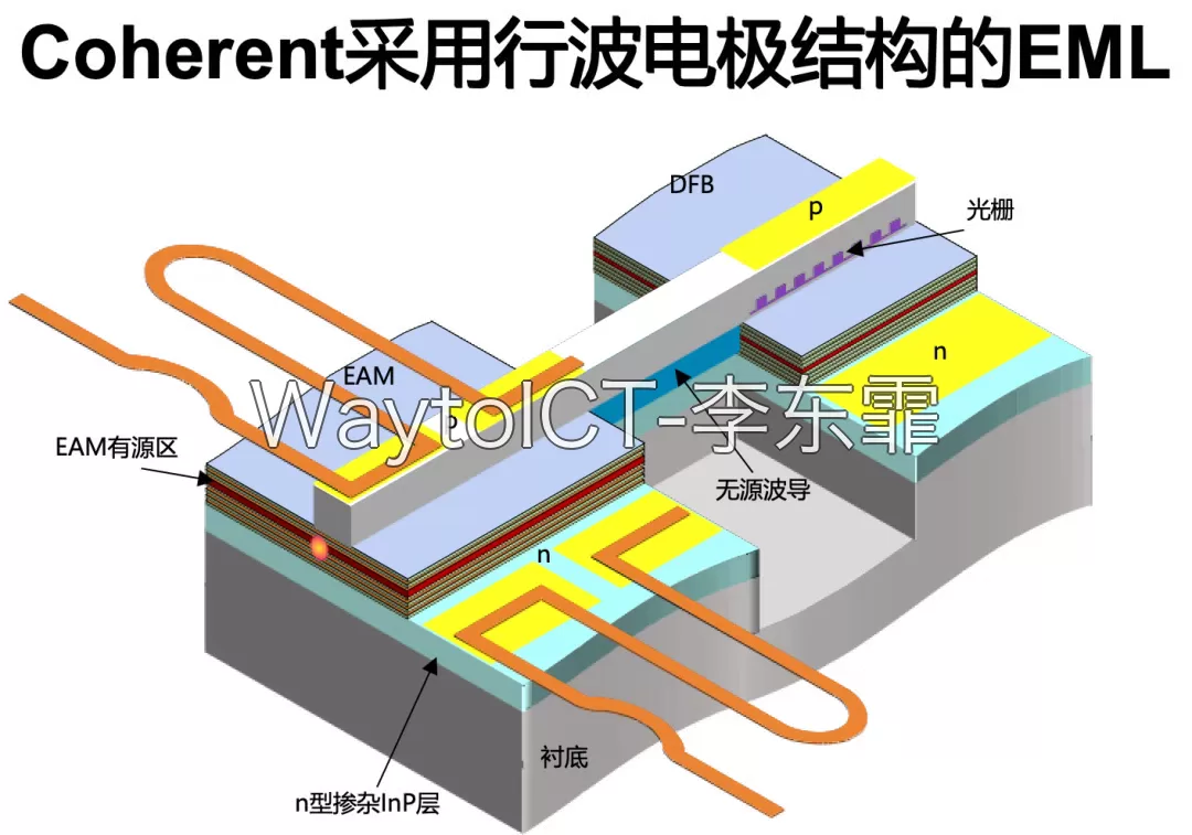
3. Evolution of Modulation Electrodes: from Lumped to Traveling-Wave
As EML data rates advanced from 25G to 100G/200G/400G/lane, the electrode structure continued to evolve:
- Lumped electrode: an early structure with short electrodes and large parasitic capacitance; the 3 dB bandwidth is typically ≤ 25 GHz, supporting only 25G/50G NRZ;
- Segmented lumped electrode: the EAM is divided into multiple sections driven separately, reducing the capacitance of each section and pushing the bandwidth to around 40 GHz;
- Traveling-wave electrode: a coplanar waveguide carries the RF signal along the EAM so that the optical field and the microwave maintain velocity matching in the propagation direction, with a serpentine trace compensating the inductance. Combined with a BCB polymer dielectric to reduce parasitic capacitance and a termination resistor to suppress RF reflection, traveling-wave EMLs have pushed the 3 dB bandwidth beyond 100 GHz, making them the mainstream solution for 200G/lane and above.
4. Typical Application Scenarios of the EML
The EML is currently deployed mainly in the following scenarios:
- 400G/800G data center optical modules: 400G FR4 / 800G FR4 / 2×FR4 and other 2 km interconnects commonly use 4-channel EMLs;
- 1.6T/3.2T optical modules: single-lane 200G PAM4 requires even faster EMLs, and the traveling-wave electrode is a must;
- 5G midhaul/backhaul and access networks: 25G/50G PON ONU optical modules use EMLs to achieve symmetric rates;
- Coherent pluggable optical modules: coherent modules such as 400G ZR / 800G ZR+ require the EML as a low-noise, narrow-linewidth light source.
- HG Genuine: 3.2T solution progress and NPO evolution roadmap
5. EML Industry Landscape
The core EML vendors are concentrated mainly in Japan, Europe, and the United States:
- Coherent (formerly II-VI / Finisar): a major supplier of high-speed traveling-wave EMLs, with significant EML business growth in fiscal 2026, covering the full 100G/200G/400G/lane product line;
- Lumentum: a traditional EML leader; the 2025 acquisition rumor involving Cisco had a huge impact on the market landscape;
- Sumitomo Electric: a long-established Japanese EML vendor, notable for its series dual-EAM differential drive approach;
- Broadcom: accumulated EML capacity through the acquisitions of Avago, CyOptics, and others;
- MACOM: focused on 100G/lane EMLs, acquired Applied Micro in 2017;
- Domestic (China): Source Photonics (Innolume), Innolight (module maker with in-house EML), Accelink, HG Genuine, and others are accelerating breakthroughs.
6. EML Evolution Trends
Over the next 3-5 years, the EML will evolve mainly in two directions:
- Single-lane 200G PAM4 to 400G PAM4: requires a traveling-wave EML with a 3 dB bandwidth above 100 GHz, with continued optimization of the standard combination of BCB dielectric + serpentine trace + termination resistor;
- Co-packaged optics (CPO) integration: integrate the EML with the PIC and driver into the switch board to further reduce power consumption and latency;
For a more in-depth engineering-level analysis of high-speed EML modulators (differential drive, parasitic resistance, serpentine trace, BCB dielectric thickness, termination resistor, impedance matching, etc.), see our in-depth paid column:
“Coherent: Traveling-Wave High-Speed EML Solution” (paid ¥19.9) — an analysis of the circuit and package design principles of Coherent’s traveling-wave EML.
Further Reading
- Coherent FY2026 performance review: business structure and revenue overview
- Lumentum: OCS technology roadmap and industry evolution views
- Basics: understanding optical module naming
- Basics: the thermo-optic effect in silicon photonics chips
- What exactly is XPO?
Enjoy this article?
Subscribe to get new optical communication insights delivered to your inbox. Free, unsubscribe anytime.